AutoCAD Express Tools is a collection of productivity tools that extend the power of AutoCAD.
These tools are provided as a courtesy to you but are unsupported.
Autodesk does not assume any responsibility for their successful operation.
You can install the Express Tools during the initial product installation or you can add them later using Add or Remove Programs in the Control Panel.
You can access most of the Autodesk Express Tools from the Express Tools tab on the ribbon.

You can also access Express Tools using corresponding commands.
Personally, I like using Express Tools so I thought I’d write about some of my favorites here.
Super Hatch
SUPERHATCH is similar to the hatch command but it allows you to use an image, block, Xref, or WIPEOUT as a hatch pattern.
The SUPERHATCH dialog box provides several options:
Image – Opens the Attach Image dialog box for specifying the image for the superhatch pattern.
Block – Opens a dialog box for specifying the block for the superhatch pattern.
Xref Attach – Opens the Xref File Name dialog box for specifying an Xref file for the superhatch pattern.
Wipeout – Uses a wipeout object for the superhatch pattern.
Select Existing – Selects an existing image, block, Xref or wipeout object for the superhatch pattern.
Curve Error Tolerance – Specifies the error tolerance for the vector approximation of curved superhatch boundaries.
You can use the Block option to create hatch patterns on-the-fly, you can create blocks with different layers, colors and linetypes to create hatch patterns that react to layer states and plot with a variety of line weights.
You can use hatch images on surfaces to get a rendered effect.
70 lessons| Easy Level
If you are absolute beginner of AutoCAD then you can get started right from scratch using this free course.
Use 3D blocks as hatch patterns to place repeating items such as bricks, roof tiles, or fence fills in 3D drawings.
SUPERHATCH makes hatching to curved boundaries possible by traversing arc segments with a series of short straight segments.
SUPERHATCH lets you control the precision with which it traverses arc segments by allowing you to specify the maximum distance between the midpoint of any given segment and the arc.
Entering a large error value results in fewer segments and faster performance but arcs appear less smooth.
Conversely, entering a very small value results in smooth hatching along arcs but places more of a processing burden during regeneration of a drawing.
Superhatch objects are glued together using unnamed groups, therefore, they are not associative.
If you want to modify a single object that is part of a superhatch, you can use the GROUP command to turn off the selection of the group as follows:
Start the group command, (Command: GROUP), make sure that the Include Unnamed check box is selected.

Select the group. Note that “superhatch” appears in the description field for groups created by SUPERHATCH, click Selectable.

Choose OK.
The individual objects can now be modified separately.
Breakline
BREAKLINE will create a polyline and will insert the breakline symbol.
You can specify two points and the location of the breakline symbol between them.
You can control the relative size and appearance of the breakline symbol and the extension of the polyline beyond the selected start and end points.
You have the following options:
Block – Determines the block to be used as the breakline symbol.
The default block is defined by brkline.dwg.
Size – Determines the size of the breakline symbol.
Extension – Determines the length of the line extension beyond selected points.
You can create your own block for the breakline symbol by creating a drawing in the AutoCAD Express folder.
Make sure that the drawing contains two point objects that have been created on the Defpoints layer.
Those point objects determine the placement of the symbol and how the line will be broken, here are the steps:
Start a new drawing then draw the breakline symbol.
Make the Defpoints layer current, If it does not exist, create it and make it the current layer.
Use the POINT command to create a point object at each location where the line will connect with the breakline symbol, use only two points.
Save the drawing file in the Express folder of the AutoCAD installation folder.
When you start the BREAKLINE command, use the Block option to specify the drawing file for the new breakline block.
Explode Attributes to Text
BURST will explode blocks and convert attribute values to text objects.
The component objects are placed on the layer of the block and do not revert to their original layers.
The values of any attribute objects are preserved by converting them to text objects.
The exploded attributes assume the original attribute definition’s layer and style.
Synchronize Viewports
VPSYNC will synchronize one or more viewports with a master viewport.
All synchronized viewports will take on the zoom factor of the master viewport.
To give your drawing a cleaner appearance, you can place all the viewports on a separate layer and then turn that layer off after running VPSYNC so that the edges of the viewport are not displayed.
Command Alias Editor
ALIASEDIT will allow you to create, delete, and modify command aliases.
Aliases can be created for AutoCAD or DOS executable commands.
There are two tabbed sections, command Aliases and Shell Commands.
Options common to both sections include:
Add – Displays a dialog box that allows you to add a new AutoCAD alias and command or DOS alias, command, and prompt.
Remove – Removes AutoCAD or DOS command alias from the acad.pgp file.
Edit – Displays a dialog box where you can edit the currently selected AutoCAD alias and command or DOS alias, command, and prompt.
Confirm Changes – Turns the display of the confirmation dialog box on or off.
OK – Saves changes and exits Alias Editor
Close – Exits the Alias Editor without saving changes. Any changes made before the Apply button was clicked are saved.
Apply – Saves changes in progress, and then allows you to continue editing.

System Variable Editor
SYSVDLG will allow you to view, save and edit system variable settings.
It is important to note that no changes are saved to the drawing until you choose OK.
All of the pending changes can be discarded with the Cancel button.
New system variable values are validated as they are changed.
The dialog box includes the following options:
70 lessons| Easy Level
If you are absolute beginner of AutoCAD then you can get started right from scratch using this free course.
List Box – Displays a list of system variables.
The edit field above the list box allows for filtering the list box display based on user input. If nothing is entered in the edit field, the list will display all of the system variables.
If more than one system variable is highlighted, all of the edit and display options are unavailable.
New Value – Displays the current value of the system variable highlighted in the list box and allows you to edit that value.
No changes are committed until the dialog box is closed with the OK button.
The edit field will be unavailable if the selected variable is a read-only type.
Current Value – Displays the value of the system variable that is highlighted in the list box as of when SYSVDLG was started.
Initial Value – Displays the initial value of the system variable highlighted in the list box. This is the value that the system variable has in a new drawing.
Saved In – Displays where the value of the highlighted system variable is saved.
Type – Displays the type of the highlighted system variable.
Save x – Saves the current system variable settings to an SVF or SCR file.
SVF files can be read into SYSVDLG. SCR files are AutoCAD scripts, which can be run from the AutoCAD command line.
The button will display Save All, Save Filtered or Save Selected, which depends on the condition of the system variable list.
If only one system variable is selected and the list is not filtered, then all of the system variables will be saved.
If more than one system variable is selected, then only the highlighted items will be saved.
If the list has been filtered, as with a wildcard, the list is saved as displayed.

Calendar Date
JULIAN contains the DATE tool and several AutoCAD Julian date and calendar date conversion routines.
JULIAN is not meant to be entered in the Command window.
Enter DATE to display the current date and time in this format: Day YYYY/M/D HH:MM:SS.msec.
DATE uses (JTOD) to convert to calendar format and edits the date and time from there. Use the syntax indicated for the following AutoLISP functions:
CTOJ Converts calendar date and time to Julian date Function syntax:
(ctoj <year> <month> <day> <hour> <minute> <second/fraction>)
Input: Calendar date as argument list Returns: Julian date / fraction, as in the DATE system variable
DTOJ Converts AutoCAD calendar date/time to Julian date Function syntax:
(dtoj <calendar date>) Input: Real number YYYYMMDD<.HHMMSSmsec>, like CDATE setvar. Returns: Julian date / fraction, as in DATE system variable
JTOC Converts Julian date to calendar date list Function syntax:
(jtoc <Julian date>) Input: Real number <Julian day>.<fraction>, like DATE setvar Returns: Calendar date/time list: (<year> <month> <day> <hour> <minute> <second/fraction>)
JTOD Converts Julian date to AutoCAD calendar date/time Function syntax:
(jtod <Julian date>) Input: Real number <Julian day>.<fraction>, like DATE setvar Returns: Calendar date/time, as in CDATEsystem variable
JTOW Determines day of the week for a given Julian day Function syntax:
(jtow <Julian date>) Input: Real number <Julian day>.<fraction>, like DATE system variable Returns: Integer day of the week, 0 = Sunday, 1 = Monday, 6 = Saturday
To access the read-only DATE system variable instead, use (getvar “DATE”).
70 lessons| Easy Level
If you are absolute beginner of AutoCAD then you can get started right from scratch using this free course.
Layout Merge
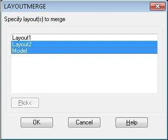
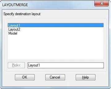
LAYOUTMERGE combines specified layouts into a single layout. A Command line version, -LAYOUTMERGE is also available.
The prompts appear as follows:
Specify layout(s) to merge or [?]: layout1,layout2 Enter layout names and/or wild cards separated by commas

Specify destination layout or [?] <Model>: Specify an existing layout name or enter a new name to create a new layout.

Delete unused layouts? <Y>:
Each merged layout will have a corresponding saved view in the destination layout and will be labeled with a rectangle and text identifier on the DEFPOINTS layer.
Object Handle IDs are changed for all merged objects.
Offset
EXOFFSET offsets selected objects.
This enhanced version of the OFFSET command offers several advantages over the standard command, including layer control, undo and a multiple option.
The following options are available:
Distance – Offsets the selected object a specified distance
Through – Offsets the selected object through a specified point
Layer – Specifies the layer for new objects, either the current layer or the layer of the source object.
Gaptype (automatically applied) – Uses the current setting of the OFFSETGAPTYPE variable to create extended, filleted, or chamfered corners to fill potential gaps in offset polylines.
Multiple – Creates multiple offsets.
Pressing Shift while specifying a side to offset acts as a multiple option and selects the new object. Pressing Ctrl while specifying a side to offset erases the original object.
Summary
So these are my favourite express tools that I regularly use.
Do you use an express tool that you think will make a great addition to this list?
Let me know in the comments down below.


