Making a Floor Plan in AutoCAD from Scratch
AutoCAD is a powerful software used by architects, engineers, and designers to create and design standard floor plans for any project. In this step-by-step project-based article, I will guide you through key processes for creating a standard floor plan from scratch. These include setting up the correct drawing template, making walls with lines and offset, [ ]
AutoCAD is a powerful software used by architects, engineers, and designers to create and design standard floor plans for any project.
In this step-by-step project-based article, I will guide you through key processes for creating a standard floor plan from scratch.
These include setting up the correct drawing template, making walls with lines and offset, adding details to your floor plan, adding blocks and appliances, adding doors and windows, and utilising layers.
A video tutorial is also available for a more detailed walkthrough.
1. Setting up a drawing template.
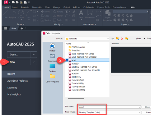
Begin by launching AutoCAD and selecting a ‘New’ drawing with the basic acad.dwt template as shown below.
Next, use the UN command to define the units in the Drawing Units window, either Imperial (feet and inches) or Metric (millimetres/ meters).
For this instance, I will use feet and inches as the units for this project.
Save the AutoCAD drawing as a template to use it for future projects.
Attaching Floor Plan Image in AutoCAD
In this example, I will attach an external floor plan image, a condominium floor plan that I will use to draw the new floor plan.
To do so, use the IM command to open the External Reference palette, from where you will choose the Attach Image option as shown below.
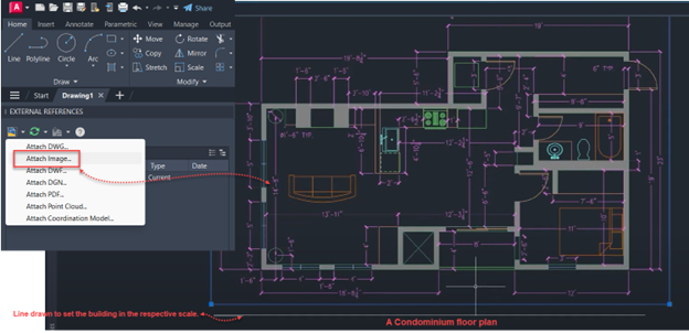
To set the image per your scale, begin by drawing a line that replicates the total length of one side of the floor plan, preferably the longest span as depicted in the image above.
Next, scale up your image using grip editing mode to stretch and align the image with the line drawn to scale.
Grip editing includes other modes such as rotate, move, scale, and mirror commands, which can be activated using the spacebar while in grip editing mode.
2. Drawing Walls with lines and offsets
Once your image is set, you can now create the walls.
Walls can be created using either the Rectangle or Line command, but in this case, I will use the Line command because the floor plan is not rectangular in shape.
Start by outlining the outer walls of your floor plan.
To do so, activate your Line command by typing LI in the command bar and pressing Enter.
After you are done outlining your lines, cancel the Line command, using the Escape key or by right-clicking and selecting Enter.
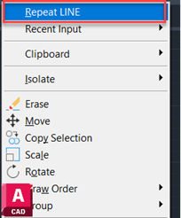
To repeat the Line command, right-click and select Repeat Line.
To have proper lines, enable the Polar Tracking tool for flexible angle snapping, the Ortho Mode tool to limit movements in horizontal and vertical directions and/or the Object Snap to allow precise location and attachment of specific points on objects in your drawing, such as Endpoint, Node, Centre, Intersection, Perpendicular, etc.

Navigate to the Utilities Tab under the Home tab and select Measure or type in DI in the command bar to enable the Measure command to confirm all the lengths of the lines drawn in your floor plan.

Drawing the inner walls in AutoCAD
After drawing the outer boundary of the wall, use the Offset command to draw the inner walls.
To enable the Offset command, type in O in the command line or under the Modify tab, select the Offset icon.
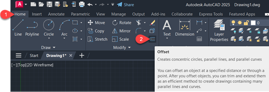
With the offset command activated, select each line to offset, then input the distance you want to move the new lines.
Alternatively, join the outer boundary wall lines to be one enclosed sort of loop by enabling the Join command, then highlight all the lines and press Enter.
Use the same Offset and Line command to now draw the partition walls in the floor plan.
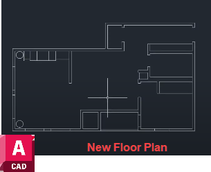
Here is my new created floor plan.
3. Adding Details to a floor plan using AutoCAD
Inserting doors and windows.
Once the walls are complete, you can now add doors and windows to your floor plan.
To draw the windows on your floor plan, you can draw, extend or offset lines where the windows and door openings will be located, then trim the line extensions as illustrated below.
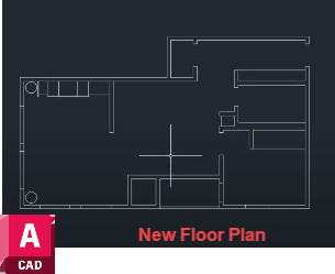
To trim unnecessary lines, navigate to the Modify tab, then click on Trim.
In the drop-down menu, you will find the Extend command, which can be activated by holding down the Shift Key while at the trim command.
Use the AutoCAD commands discussed in this article and the video to create your living room area, bedroom, and other room spaces in the floor plan.
4. Adding Blocks and Appliances using the AutoCAD Design Centre
Blocks are named groups of either 2D or 3D objects and are used to create repeated drawing symbols, standard details and common components.
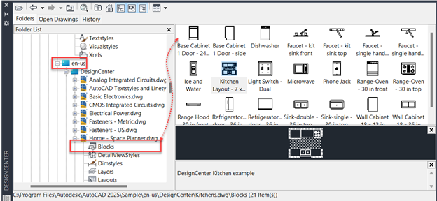
To access the blocks, type in ADC in the command line to open the Autodesk Design Center.
In the floating window palette, click on the Home icon and navigate to a default folder called Sample.
Navigate to Sample drawing and select Floor plan.dwg then select Blocks.
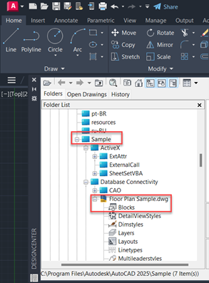
Alternatively, you can navigate to the en-us folder, click on Design Center, and load the blocks from various templates, such as welding, landscaping, pipe fittings, Kitchens, HVAC, Electrical Power, etc.
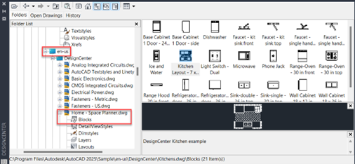
To place your furniture and appliance blocks in the floor plan, simply select an item and drag it onto the floor plan drawing.
Click any items placed on your drawing to activate the grip editing mode settings.By this, you can move, rotate, stretch, or mirror your items in the floor plan and place them in their respective room space.
Placing Doors and Window Blocks
Windows and doors can be loaded into the floor plan as dynamic blocks.
They have grips that can be used to easily flip them, set wall thickness, change the angle at which the door opens, etc.
The advantage of using dynamic blocks is that you can easily manipulate, copy, and place them in different areas of your floor plan.
To place them, simply drag and place them in your floor plan.
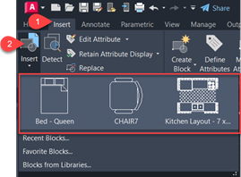
You can view the loaded blocks in your drawing under the Insert tab.
Setting block Line types and scale in AutoCAD
To change the line type of your elements, open the Properties menu, and under line type, you can change it to the line type you will have loaded.
To load the line type, open the line type manager by typing in LT then click on Load to choose your preferred line type.
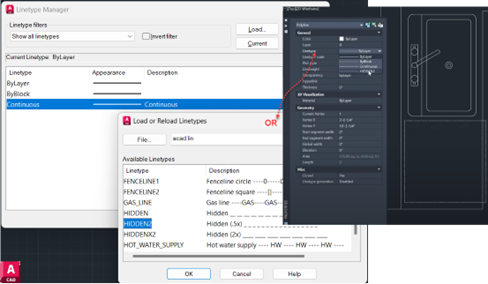
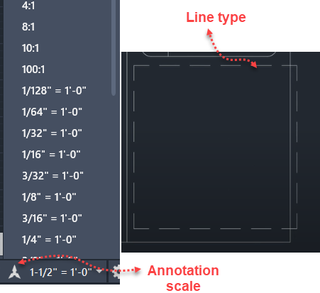
To set the line type scape, type in LTS in the command bar and input the new line type scale factor, after which you will regenerate the model by typing in RE in the command line, and your lines will adjust to the set scale.
Alternatively, change the annotation scale and then regenerate the model.
Viewing and Deleting Blocks
To view the blocks present in your drawing, navigate to Insert Tab, and select Insert,A list and preview of the blocks will be displayed.
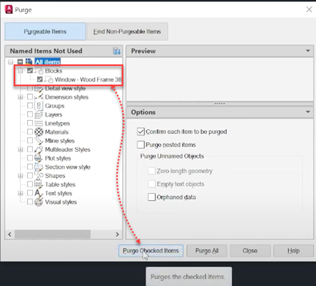
To completely remove blocks that are completely not referenced in the drawing, use the Purge command for this purpose.
5. Utilising layers
Now that we are done with the geometry of the floor plan, I will now input the layers.
Layers are particularly important in drawing your floor plan because they are used to help differentiate items in your drawings.
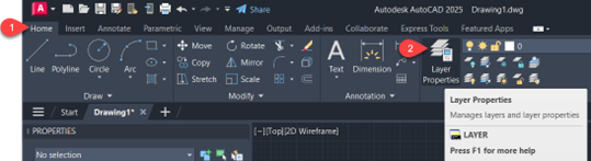
To open Layer Properties Manager, navigate to the Home tab and select Layer Properties.
Alternatively, you can type in Layer in the command line, and a Layer properties manager pop-up window will open.
Start by creating new layers for each type of object present in your project drawing.
Click on the New Layer icon to create new layers for each object in your project.
Here, you can assign a particular colour (use the index color palette), line weight, line type, and description to the layers.
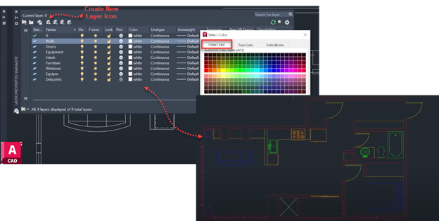
In the Layer Properties Manager popup window, you can lock or freeze layers to avoid accidental changes to certain parts of your project design.
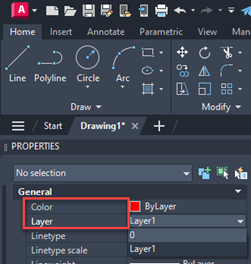
To assign the layers to the objects, select the object, then under the Layers panel, choose the layer to assign to the object selected, for example, walls, windows, etc.
Alternatively, in the Properties menu, select the object and assign the layers.
Layer Translation in AutoCAD
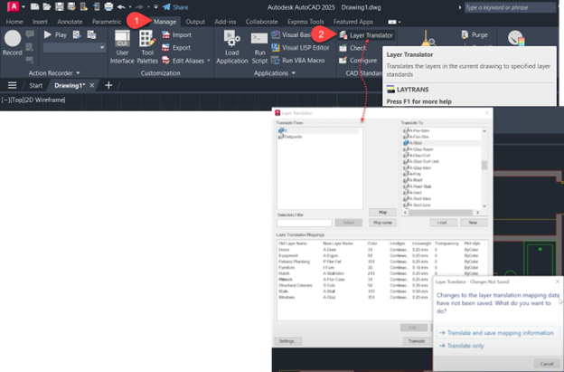
Layer Translator is used to manage the job of mapping non-conforming layers in your drawing to your preferred standards.
To execute that, navigate to the Manage tab and select Layer Translator under CAD Standards.
A Layer Translator window will open, and here you can translate and map the layers.
Frequently Asked Questions:
Can I adjust the scale of my floor plan?
Definitely, yes!
To adjust the drawing scale, use the annotation scale.
Can dynamic blocks be used for furniture in my floor plan?
Yes!
Dynamic blocks can be used to place the furniture.
They allow you to resize or rotate them without creating new blocks.
How do I create blocks to use in AutoCAD?
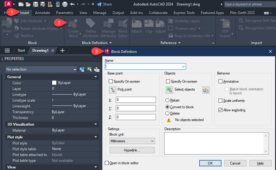
Navigate to the Insert tab, click Create Block, and then in the Block Definition pop-up window, assign a name and insertion point for the block, then save it.
Summary
By following the steps in the article, you can now create a floor plan.
Watch the video version of this article to follow through with an example that offers detailed steps.
For any queries, kindly leave them in the comment section below.