How to use xRef in AutoCAD, a complete step by step guide
External Reference in AutoCAD AutoCAD External References (Xrefs) is a powerful feature that allows you to integrate external files seamlessly into your primary drawing, making collaboration possible within your projects. Xref in AutoCAD offer benefits like collaboration, organization, streamlined editing, and error reduction. In this guide, we ll walk you through everything you need to know [ ]
External Reference in AutoCAD
AutoCAD External References (Xrefs) is a powerful feature that allows you to integrate external files seamlessly into your primary drawing, making collaboration possible within your projects.
Xref in AutoCAD offer benefits like collaboration, organization, streamlined editing, and error reduction.
In this guide, we’ll walk you through everything you need to know about AutoCAD External References using a practical example with a DWG file.
You can download the lesson files used in this tutorial here.
Also, if you prefer the video then here it is, else read on.
Understanding AutoCAD External Referencing
AutoCAD External References, or Xrefs, enable you to insert various files such as DWG, images, PDFs, and point cloud data, into your drawings.
The idea of Xref is that you can have different people working on the project, each person working on a specific component which can be integrated into one component using the Xref feature.
Using Xrefs with a Drawing (DWG) file
Imagine you’re working on a building project and have separate drawings for the floor layout, electrical plans, plumbing, and furniture.
Multiple people from a team can work on different parts of the project and then all these separate parts of the project can be easily integrated into a master drawing while preserving individual editability.
Before we start attaching external drawings we need to set Up the Host Drawing.
Assuming you do not have any previous drawing, you can start by creating a new drawing for the building’s layout plan, designated as the “host drawing” as this will serve as the foundation for integrating external references.
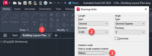
In this case, open a new drawing in AutoCAD then type UN and press enter to open the unit command palette.
Change the units to meters, with a decimal place of three (3), and then save the drawing as a “Building layout plan” as shown below.
You can now Attach your External References.
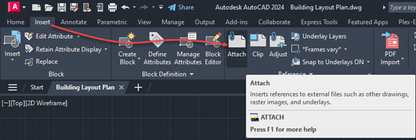
You can either use the XREF or ATTACH command, to insert external references into the host drawing.
Additionally, under the insert tab, reference panel, you can find the Attach command as shown below to bring your external reference drawing into AutoCAD.
Once the command is active, the Select Reference File menu will pop up, from where you can select the file of your choice from the supported format in AutoCAD (All image files, DWF. File, MicroStation DGN. file, All DGN. files, PDF files, AutoDesk Point Cloud file, Navisworks file, and Drawing file).
If you had used the XREF command, the External Reference palate would have popped up, and under the file reference window, right-click on your mouse to activate the various attached file options mentioned above as shown in the following image.
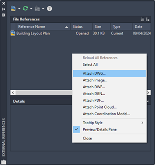
In this case, select Attach DWG and then the Select Reference File menu will pop up.
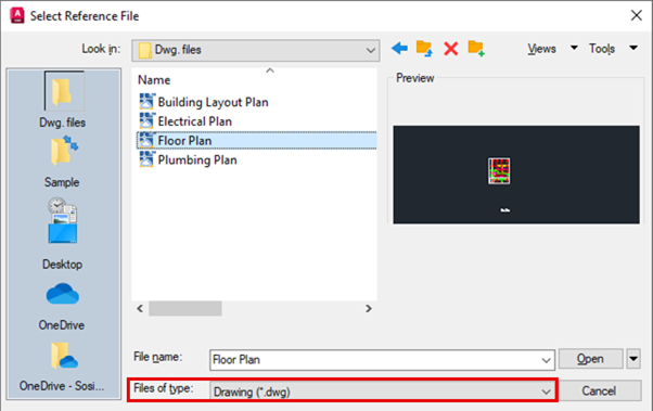
In this case, you will be working with the Drawing file (Dwg.), select the Floor plan file as shown below and click Open.
Make sure you have Drawing (*.dwg) selected in the Files of type menu as shown in the following image else the DWG files won’t show up in the folder.
After selecting the file and clicking the open button the Attach External Reference menu will pop up.
Under the menu you can adjust your Scale, Path type, Insertion point, Reference type, etc.
For our example, make sure points 2, 4, and 5 have been left unchecked, to ensure you are working with the defaults.
For other options, leave everything as shown below, and click on OK.
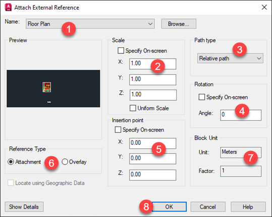
Before we move further let’s explore the options in the Attach External Reference options window.
Point 1:
The Name option is usually a drop-down list that you can use to select the appropriate DWG file that you want to import. You can change the xref attached to the list by click on browse and select by selecting a new document.
Point 2:
The Scale option allows you to alter the scale of the DWG file that you are importing.
You can opt to input only one value by checking the Uniform Scale option; or in the event you want your drawing to have different scales for different axes, you can input the values separately.
By leaving the Specify On-screen option checked, AutoCAD will prompt you to select the scale within your workspace.