The first angle and third angle projection system are common terms that you must have seen in technical drawings.
These projection systems are used to represent the features and dimensions of a 3D orthographic drawing on a 2D plane.
In this article, we will learn all about first-angle and third-angle projection systems.
Why use a projected system for dimensioning?
Dimensioning in 3D is just not practical, you can’t keep the text direction proper, adding tolerances is a nightmare and defining datums can sometimes be ambiguous.
For all these reasons 2D projected views are used for 3D drawings.
As an example take a look at the drawings shown below.
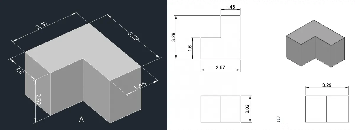
In drawing A dimension is added directly to the orthographic view of the 3D part but in drawing, B dimensions are added using projected views of the orthographic view.
In drawing A adding dimensions is tedious with several changes required in dimension style for every single dimension.
Moreover, it’s good for a simple non-technical drawing where you just need to show simple dimensions but no other information like manufacturing process, surface roughness, tolerances and more.
If you try adding all these details in a 3D drawing containing features like fillets, holes, threads, surface roughness and more then it will fill the space around the single 3D drawing making it cluttered.
On the other hand, we can easily add different technical features and dimensions on different views of the drawing and this will keep all the dimensions clear and non-ambiguous.
What are the angles of projection?
We can divide 3D space into four quadrants as shown in the figure down below.
Here the entire 3D space is divided into four quadrants using two projection planes, a horizontal (yellow plane) and another vertical (Purple plane) one.
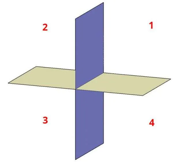
If the object is placed in the first quadrant of this 3D space and its views are created on the horizontal and vertical projected planes of the first quadrant then the views thus created are said to be in the first angle of projection.
Similarly, if it’s in the third quadrant then it’s called the third angle of projection.
We don’t use the 2nd and 4th quadrants and I will explain later why it’s the case.
Now let’s talk about the first angle of projection and how its views are created using projection planes.
The first angle of projection
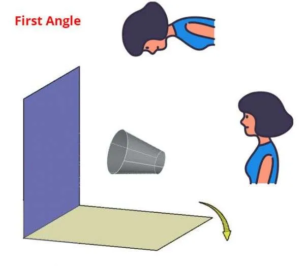
Let’s take the first quadrant from the 3D space we saw earlier and place the 3D object in it.
The object will be viewed by an observer from the top and right sides.
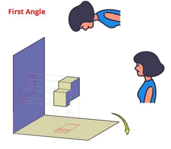
So when the object is placed in the first quadrant, and the viewer looks at these objects from the right side and from the top then she will see a view that looks like the 2D drawings (shown in red) created on the horizontal plane and vertical plane as shown in the figure above.
In simple words, we can say that if a torch is lit up from the top, it creates a shadow that falls on the plane below the object so the top view is created at the bottom of the object.
Similarly, if a torch is lit up from the right side of the object, it creates a shadow that falls on the plane on the left of the object as its projection.
So the view from the right side is created on the left of the object.
In this case, our object falls between the observer and the projection plane.
This is an important observation as this same system can be used to create other projected views as well.
Now assume that our projected shadow is permanently imprinted on the planes and then we decided to make these planes flat by moving the horizontal plane in the clockwise direction.
The resulting projected drawings will look like the image shown below.
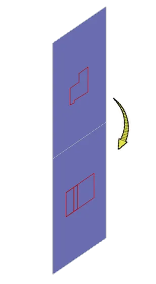
As you can see in these projections the view from the top is now at the bottom and the view from the right is above the top view.
For creating the other views in the first quadrant all you need to do is place the object between the observer and projection plane.
So, if you look at the drawing from the left its projection will be made on a plane on the right, if you look at it from the front its projection will be made at back and so on.
So, the final projection views of this drawing in the first angle of projection will look like the following image.
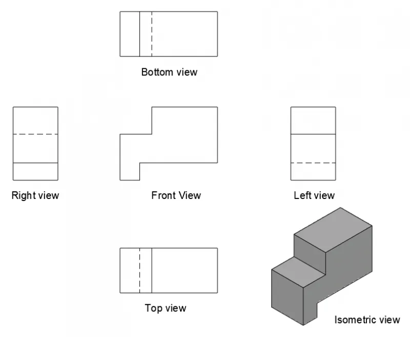
This projection system is most common in India, Europe and other Asian countries.
The third angle of projection
Now in the third angle projection, the object is placed in the third quadrant as shown in the following figure.

Here once again the observer is at the right side and at the top.
But in this case, the plane of projection is between the observer and the object.
So, here the view from the top is created on the projection plane which is already above the object and the view from the right is created on the right plane which is once again before the object.
Once again rotate the horizontal plane in the clockwise direction so the project views will look like this image.
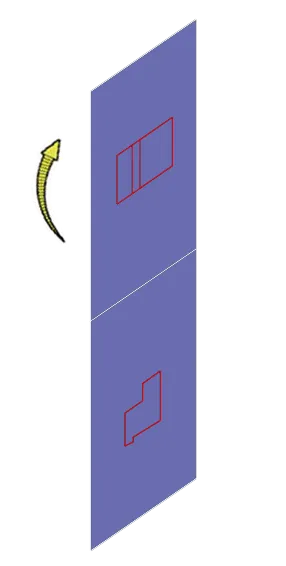
So, in this case, the top view is now at the top of the drawing and the right side view is below the top view.
For creating other views in the third quadrant all you need to do is place the projection plane between the observer and object.
As the projection plane comes right after the observer and before the object, the view of the respective side will be created on the same side.
So the right side view will be on the right, the left side view will be on the left, the top view on top and the bottom view on the bottom.
The final projection views of this drawing in the third angle of projection will look like the following image.
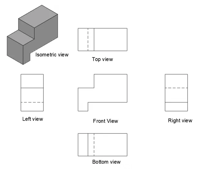
This projection system is most widely used in the United States of America and Australia.
Why second and fourth angles of projection are not used?
It all comes down to one simple rule of orthographic projection.
The horizontal plane is rotated in a clockwise direction to create the projected views.
So, if you rotate the horizontal plane in the clockwise direction you will end up with horizontal and vertical planes merging with each other in the second and fourth quadrants as shown in the following image.

With this, the projected views will also merge and you will end up with drawing views that are on top of one another and completely obscured.
So, that’s the reason we don’t use the second and fourth angles of projection.
About projection symbols
The first and third angles are represented by the symbols shown below.
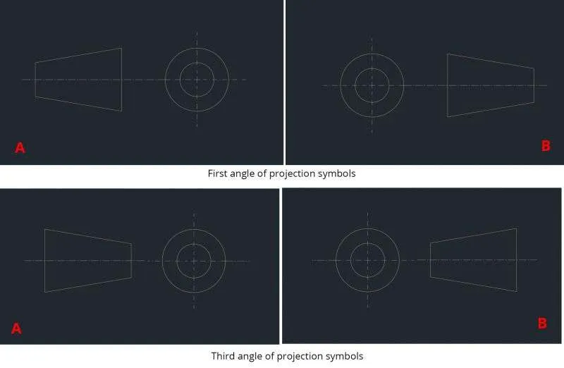
Here both the symbols A and B are acceptable symbols of the first angle of projection.
Now, the question is why are these specific symbols used for the first and third angles of projection?
Let’s start with the 3D drawing of our cork shape of the drawing in the first angle of projection.
If we look at the cork from the right side in such a way that observer is looking at the smaller diameter side of the cork then the project view created will show one circle on the purple projected plane, not two concentric circles.
If however, we look at this cork from the left side in such a way that the observer is looking at it from the larger diameter side then the projection on the opposite side will contain two concentric circles.
So, here the view from the observer’s perspective is on the opposite side, the left view is on right and the right view is on left and that is happening with the first angle o the projection symbol.
Though the concentric circles are visible from the side of smaller diameter the concentric circles are placed on the opposite side i.e. the side of larger diameter.

Both are acceptable symbols of the first angle of projection
In the case of the third angle of projection, the observer view and projection are on the same side so the two concentric circles are visible from the smaller diameter side and the concentric circle are also placed on the smaller diameter side of the drawing.

Both are acceptable symbols of the third angle of projection
In the following section, I have added a summary of the difference between the first and third angles of projections.
Summary
In a nutshell, if you stand on the left side of the object and the same view is represented on the left side of the drawing then that is the third angle of projection, similar for other views as well.
If however, the views are on opposite sides then it’s the first angle of projection.
Here is a summary of the major differences between the first and third angles of projection.
The first angle of projection | The third angle of projection |
|---|---|
The object is placed in the first quadrant of the 3-dimensional space. | The object is placed in the third quadrant of the 3-dimensional space. |
The object falls between the observer and the projection plane. | The projection plane falls between the object and the observer. |
The concentric circle of the projection symbol is on the larger diameter side. | The concentric circle of the projection symbol is on the smaller diameter side |
The First Angle of projection is commonly used in India, Europe, and other Asian countries | The Third Angle of projection is widely used in United State and Australia. |

