If you are wondering how to import coordinates from Excel to AutoCAD (Easting, Northing & Reduced Levels) then this article will help you do that using two different methods.
In the first method, we will use only Excel to compile data and then we will simply import the data in AutoCAD.
In the second method, we will transfer the data from Excel to a simple script file and then we will import the script file in AutoCAD to make the points.
The video version of this article is added below, if you prefer the article then read on.
Importing coordinates using Excel formula
As shown in this pic below, we have X, Y, and Z coordinates, otherwise Easting, Northing & Reduced levels of more than 10000 points in an Excel sheet.
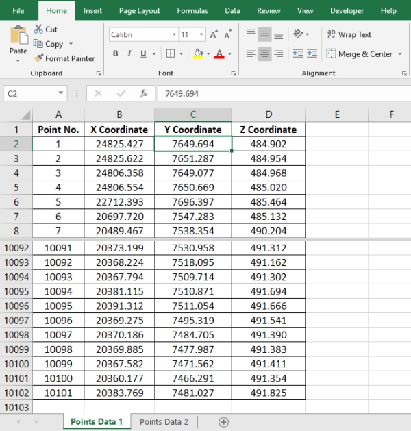
To create points using this data (to Export this data into an AutoCAD drawing), we have to convert this data into the language that AutoCAD can understand.
70 lessons| Easy Level
If you are absolute beginner of AutoCAD then you can get started right from scratch using this free course.
Converting data for AutoCAD
We can convert this data in coordinate points and AutoCAD uses POINT Command to make points in AutoCAD.
Type in POINT in the command bar and hit the Enter key.

Now we have a message at the Command Prompt, ‘Specify a Point’, There are two methods to specify a point.
Feed the X, Y, and Z Coordinates of the Point in the Command Bar.
Click anywhere in the drawing area and an AutoCAD point Object will be created at that particular point.
Here I will go with the first method i.e. feeding the X, Y, and Z Coordinates of the Point in the command bar, let it be 1000,1000,1000.

Press the Enter key and an AutoCAD point is created at 1000,1000 with an elevation of 1000, see the animated gif above for reference.
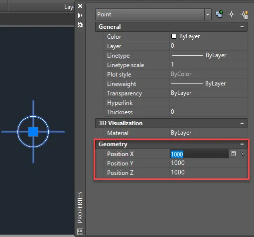
If you want to verify the coordinates of the point you can do that using the Property Palette.
Select the Point, Right Click, and select Properties from the menu.
Values which we used to create this point are shown against the labels Position X, Position Y, and Position Z as shown in the image below.
The sequence of commands used to create the point can be replicated approximately 10,000 times to create all the points but obviously, it can’t be done manually and this is where the Excel formula comes into the picture.
The flow of command for POINT looks like this on the command bar history.

Here is the flow of the command shown in the image above.
Command: POINT
Current point modes: PDMODE=0 PDSIZE=0.0000
Specify a point: 1000,1000,1000
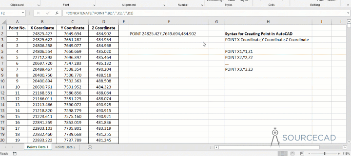
In our Excel sheet, the X, Y, and Z Coordinates of Point 1 are in the cells B2, C2 and D2 respectively.

From the command history, it is clear that the syntax for creating a point in AutoCAD is POINT X, Y, Z.
Creating point coordinates
So for 10,000 points, this value should be repeated as many times.
The resulting data should look like data inside the red box of the image below.
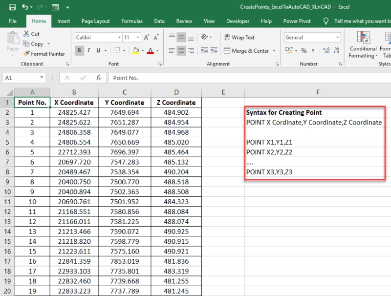
For creating a point using the coordinates given in the cells B2, C2 and D2, we have to join the data in the cells B2, C2 & D2 preceded by the POINT command.
Then we can use CONCATENATE function in Excel to join the strings.
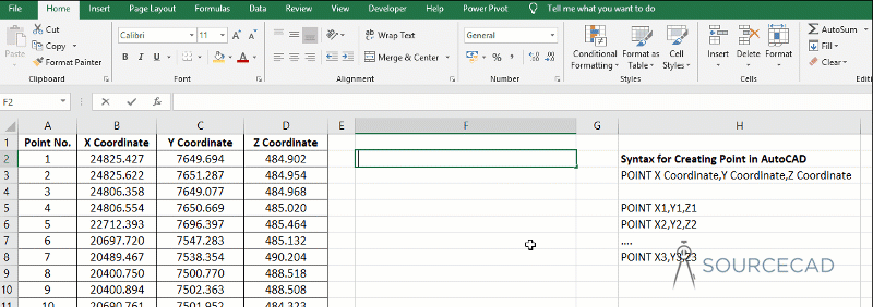
In the image above the CONCATENATE function is used to join the strings, for your reference, I am writing the complete formula here as well.
=CONCATENATE(“POINT “,B3,”,”,C3,”,”,D3) is the formula to join the 5 strings listed below.
- POINT (AutoCAD Command)
- “ “(Space Character)
- B2 (the cell containing the X Coordinate)
- C2 (the cell containing the Y Coordinate)
- D2 (the cell containing the Z Coordinate)
70 lessons| Easy Level
If you are absolute beginner of AutoCAD then you can get started right from scratch using this free course.
And the result is POINT X, Y, Z, The formula can be copied into the downward cells using the fill handle feature in Excel.
Adding data in AutoCAD
Copy this data, Open an AutoCAD drawing and Paste it into the command bar as shown in the animated gif below.
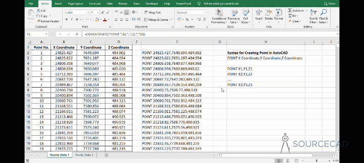
And by doing that and we just created around 10000 points.
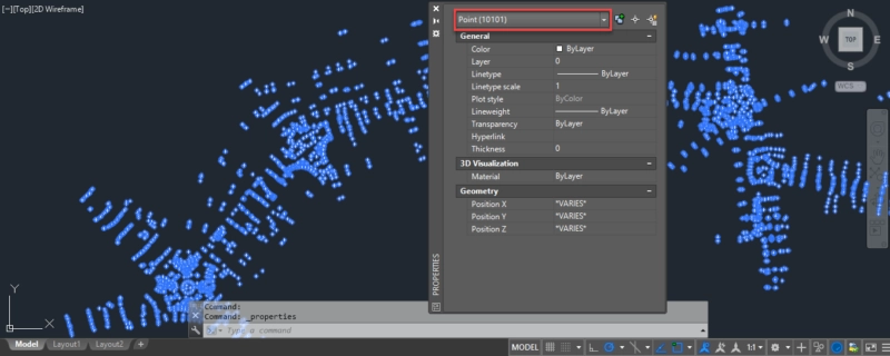
To cross-check the total number of points created, Select all (Ctrl+A is the shortcut for selecting all objects in an AutoCAD drawing), Right-click for the Properties palette and there you can see the total number of points in the drawing.
We can also use Command Aliases in the formula, command Alias for Point Command is PO.
The formula will then become, =CONCATENATE(“PO “,B3,”,”,C3,”,”,D3)
Using Script file to import coordinates
There is also another method which works in a similar way and it makes use of the script file of AutoCAD.
Again, let’s assume we have our coordinate data in an Excel sheet in three columns namely X, Y and Z (or Northing, easting and elevation if you prefer).
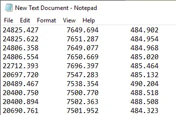
Now copy data from all of these cells then open Notepad or any other simple text editor and paste the complete data in it, this process is shown in the video below.
You data will look like the image shown below, with lots of spaces between the values of respective cells.
We need to replace the spaces here with the comma.
Select the space between respective cell entries and go to the edit menu of Notepad and select the Replace option.
Now in the replace with field, type “,” (without quotes) and press replace all button and close the replace window, take reference of the animated gif shown below.

Now type _MULTIPLE_POINT in the first line of the notepad text just before the coordinate values and then go to the file menu then select save as option and save the file with .scr format.
You can give it any name you want, in this example, I am using point.scr as the notepad file name.
Now we can import these points pretty easily in AutoCAD using SCRIPT command.
Type SCRIPT then press Enter key in your AutoCAD command bar and then locate the scr file you created in the example above and click on the Open button.
The points will be added in the drawing, the point command will also remain active which you can deactivate by pressing the ESC key.
Summary
That was all, I hope you have found this article useful.
If you have questions related to the article feel free to let me know in the comments below.
References: Autodesk knowledge network article


