How to add Tolerance in AutoCAD drawing [including dual dimensioning]
In this article, I will show you the step by step method of adding tolerance in AutoCAD drawing using dimension style. I will also show you the method of creating dual dimensioning where a single dimension can be represented in two different units.The most suitable way of adding tolerances is by the use of feature [ ]
In this article, I will show you the step by step method of adding tolerance in AutoCAD drawing using dimension style.
I will also show you the method of creating dual dimensioning where a single dimension can be represented in two different units.The most suitable way of adding tolerances is by the use of feature control frames but you can also add tolerances using dimension styles.
Here is a video that explains all about adding GD&T tolerance in AutoCAD drawing using feature control frame.
If however you want to add simple tolerance directly in your drawing dimensions then here is another video.
If you prefer the article then continue to read on to learn about adding simple tolerance in AutoCAD drawing.
Adding Tolerances using dimension style
Tolerances are applied to Dimension styles and you can create multiple dimension styles for the different type of tolerances.
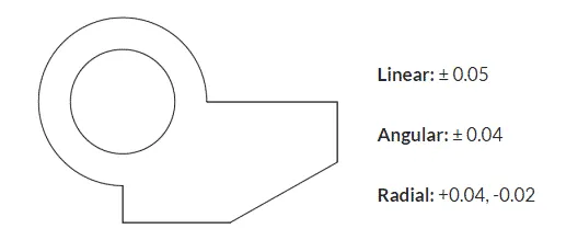
Let’s assume that we have a drawing as shown in the image below where tolerance limit is ± 0.05 for linear, ± 0.04 for angular and for radial dimension it is 0.04 upper limit and 0.02 lower limit.
For this case, we can create a dimension style and then apply individual tolerance values using the property palette of each dimension.
Type D on the command line and press enter.
Click on the New button then select a name for your dimension style and click on the Continue button.
Select Tolerances tab and from Method drop-down menu of Tolerance format panel select the Deviation option.
Don’t change the Upper and Lower values of tolerance, keep it at its default value of 0 as shown in the image below.
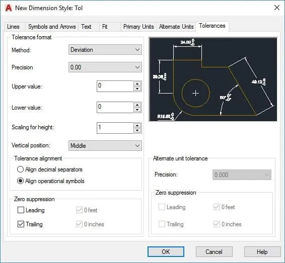
Click OK to close the Dimension style manager window.
Now make dimensions on the geometry and you will notice that it will be made with tolerance value of 0 for upper as well as the lower limit.
Select any dimension from drawing area and right click then select properties from the contextual menu.
Locate the Tolerances panel and change the upper and lower limit of tolerance from the respective field as shown in the image below.
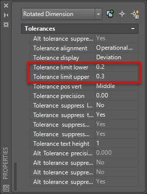
In a similar way apply the tolerance values using properties palette to other dimensions as well.
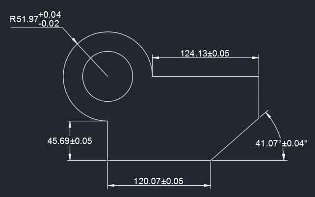
The final geometry after applying respective tolerances to the dimensions should look like the image below.
Adding Dual dimensioning
Dual dimensioning is a method of applying more than one unit to the same dimension.
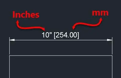
Let’s assume that we want to apply dimensions in inches as well as mm where the inch is the primary unit and mm is secondary.
For this situation, we need to first make a drawing with inches as the primary unit then type D and press enter to open Dimension style manager window.
Select the dimension style which you want to use and click on the Modify button.
Select Primary units tab and choose Architectural from Unit format dropdown of Linear dimensions panel.
Then move to Alternate units tab and click on the Display alternate units radio button.
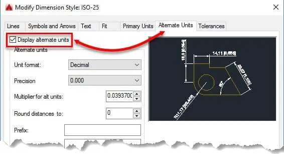
From the Unit format, drop-down menu select the Decimal and set precision of 0.00.
In the multiplier field, enter a value of 25.4, this value is obtained by converting the primary unit to the secondary unit.
In our case primary unit is inches and secondary unit is mm and we all know that one inch is equal to 25.4 mm hence the multiplier is also 25.4.
Click OK to accept the changes and close the dimension style manager window.
Now apply dimension to your drawing, you will notice that the dimension will be indicated in inches as well as mm as shown in the image below.
Summary
So, these are the simple steps of adding general tolerances and dual dimensioning directly in AutoCAD dimensions.
But you should also keep in mind that these dimensions are added as per dimensioning best practices and they should not be added out of place.
If you have questions let me know in the comment section down below.
Related reading: How to create dimension style override in AutoCAD