The Ultimate Guide to CAD File Formats Free Viewers
Over the years, I’ve juggled the ropes between different CAD software. Each comes with its own features, benefits aaaand… file formats. Whether it’s for IP protection or just business, having these closed-off formats is both a boon and a bane. We’ve all hit that wall: you send a Solidworks file to a colleague, or an [ ]
Over the years, I’ve juggled the ropes between different CAD software.
Each comes with its own features, benefits aaaand… file formats.
Whether it’s for IP protection or just business, having these closed-off formats is both a boon and a bane.
We’ve all hit that wall: you send a Solidworks file to a colleague, or an AutoCAD drawing to someone on an older version, and… snap, the collaboration breaks because they can’t open it.
It’s frustrating, flustering, and downright kills productivity.
Keeping this in mind, this guide breaks down exactly what these formats are, which software they belong to, and most importantly, how you can open them for free without buying an expensive license.
What is a CAD file?
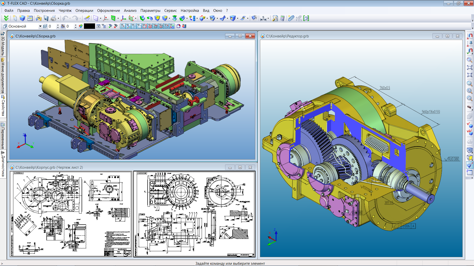
TopSystemsLTD, CC BY-SA 3.0 , via Wikimedia Commons
At their core, CAD files store geometric information about a design.
But the way they store that information varies dramatically between formats, which is why compatibility issues exist in the first place.
Some formats capture your entire design process—every sketch, every dimension change, every feature you added or removed.
Others strip away that history and just preserve the final shape. Some describe surfaces mathematically with perfect precision, while others approximate shapes using thousands of tiny triangles.
These differences matter because they determine what you can do with a file after opening it, how accurately your design transfers between programs, and how large the file ends up being.
The Two Worlds of CAD Formats
Proprietary formats belong to specific software packages. They preserve everything that you want the software to do.
You get parametric relationships, feature trees, custom properties, the whole shebang.
Butt, they lock you into their ecosystem!
Exchange formats or Neutral formats sacrifice some of that feature richness for universal compatibility.
They’re the common language different CAD software can use to talk to one another.
Neither category is “better”.
It depends on the purpose of your work.
Your original work should stay in native formats to allow you to edit better.
However, for better collaboration and handoffs, exchange formats are gold.
2D Drawing Formats
So let’s start with the very basic 2D drawing formats.
DWG: The Industry Standard for Technical Drawings
File extension: .dwg
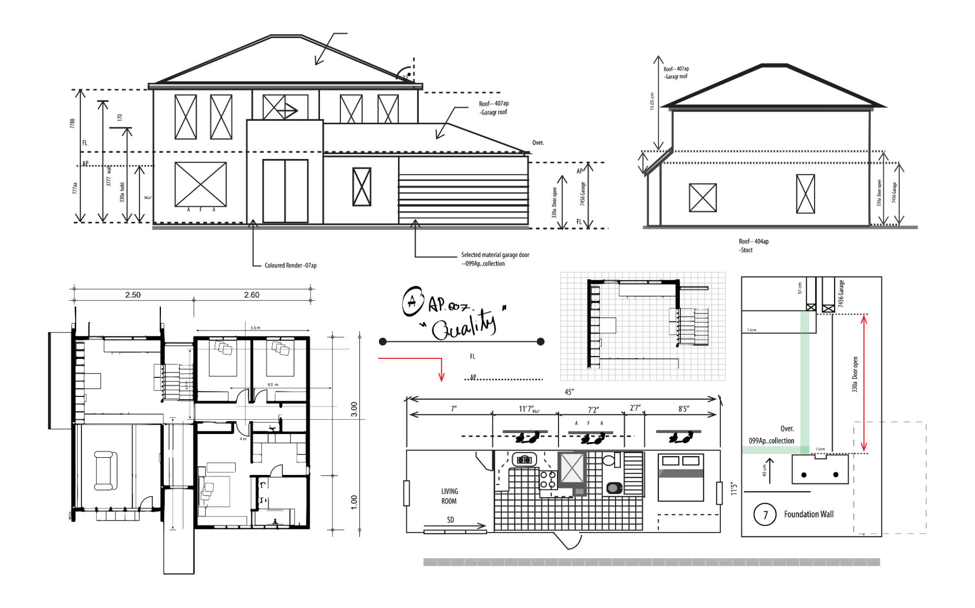
DWG dominates 2D CAD the way Word dominates word processing.
Developed by Autodesk in 1982, it stores vector graphics, annotations, dimensions, and layer information in a compressed binary format.
Nearly every architecture firm, engineering consultancy, and manufacturing facility works with DWG files.
Even CAD programs competing with AutoCAD include DWG import and export because ignoring the format means ignoring most of the industry.
Benefits:
● Extremely compact file sizes
● Rich support for layers, blocks, and external references
● Handles complex annotation and dimensioning
● Backward compatibility across versions (though imperfect)
Limitations
● Technically proprietary, though widely reverse-engineered
● Version mismatches can cause display issues
● 3D capabilities exist but aren’t the format’s strength
Where to view DWG files for free:
Viewer | Platform | Notes |
Web | Handles 80+ formats, no download needed | |
Windows | Official Autodesk viewer, includes version conversion | |
Web, iOS, Android, Desktop | Cross-platform with measurement tools | |
Web | No registration required, instant viewing | |
Web | Autodesk’s cloud platform, collaborative features |
For a comprehensive list of all free DWG viewers with detailed comparisons, check out our complete guide to 18 free DWG viewers.
DXF: The Universal Translator
File extension: .dxf
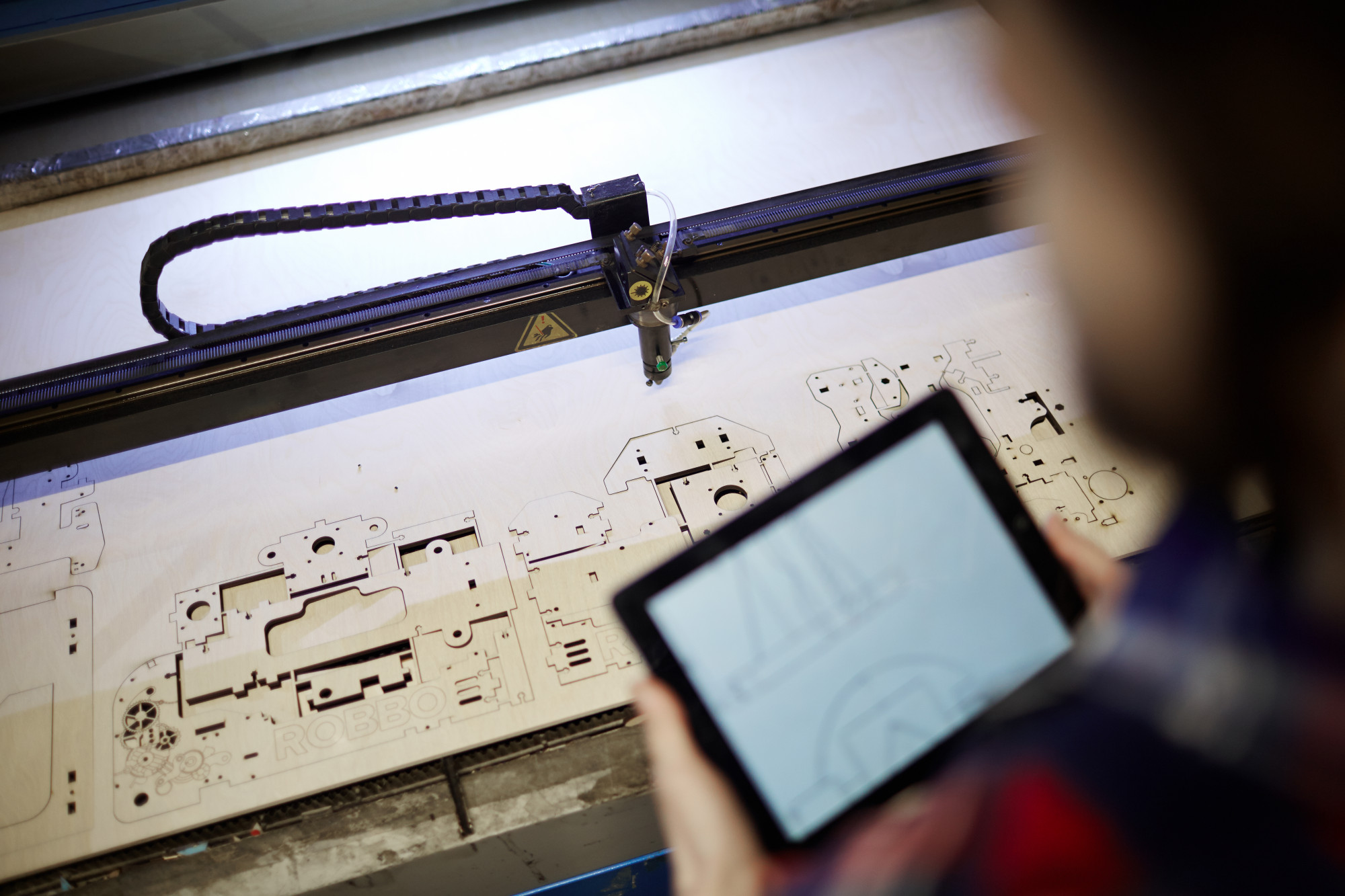
Autodesk created DXF alongside DWG specifically for exchanging data with other programs.
This format uses plain text (ASCII), meaning you can technically open the file in Notepad and read the coordinates, well, not that you’d want to.
The text-based structure makes DXF incredibly portable.
Laser cutters, vinyl cutters, CNC machines, embroidery, PCB designs, etc.—if the equipment accepts vector files, it almost always reads DXF.
Understanding how to properly export DXF files is crucial for design for manufacturing (DFM), especially when working with fabrication equipment.
Strengths:
● Opens in virtually any CAD, CAM, or vector application
● Text format survives corruption better than binary
● Perfect for CNC toolpaths and fabrication equipment
● No licensing restrictions on the specification
Limitations:
● Files run 5-10x larger than equivalent DWGs
● Some formatting and block definitions translate poorly.
● Binary DXF exists but defeats the portability purpose
Where to view DXF files for free:
Viewer | Platform | Notes |
Windows, Mac, Linux | Full open-source 2D CAD, not just viewing | |
Windows, Mac, Linux | Open-source with professional features | |
Web | The same viewer handles DXF and DWG | |
Web | Quick browser-based viewing | |
Windows, Mac, Linux | Open-source 3D CAD that handles 2D formats too |
3D Exchange Formats
These formats exist specifically to move 3D geometry between different CAD systems.
They’re designed by standards committees rather than software companies, which is why they work across competing products.
STEP: The Gold Standard for Sharing 3D Models
File extension: .stp, .step
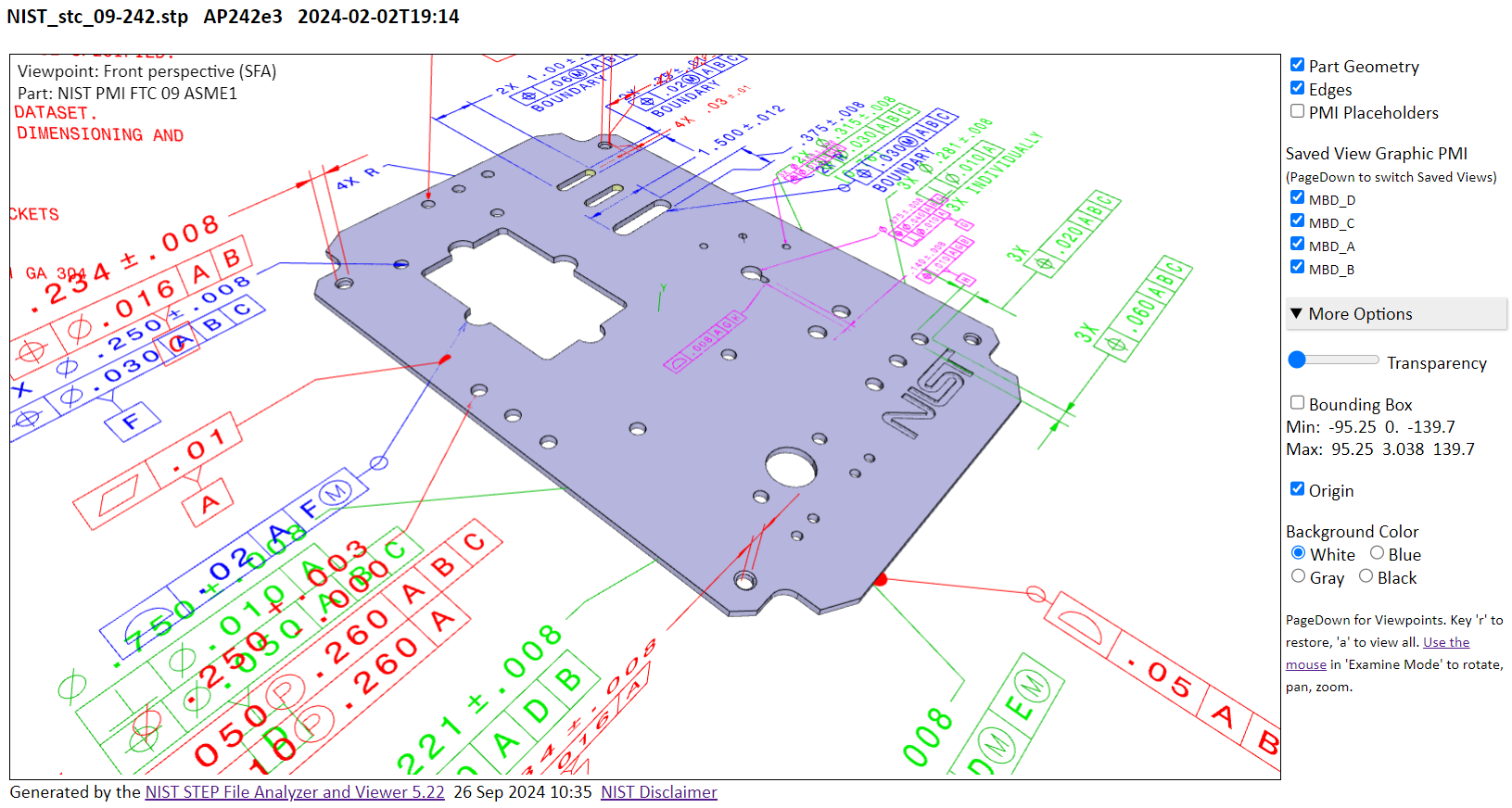
Source: https://www.nist.gov/image/nist-step-file-viewer-screenshot
If you need to send a 3D model to someone and you don’t know the software they use, send a STEP file.
The format has become so universally supported that it’s essentially the PDF of 3D CAD; almost everyone can open it.
STEP stands for Standard for Exchange of Product Data, and it’s governed by ISO 10303.
The ISO backing means the format has actual legal standing for contractual and regulatory purposes.
While it may not mean much for the average Joe designing toys in Fusion, for aerospace, automotive, and other regulated industries, the legal standing matters.
The format has evolved through several “application protocols”:
● AP203 handled basic geometry (now obsolete)
● AP214 added colors, layers, and tolerances (still common)
● AP242 is the current standard, supporting Model-Based Definition with embedded dimensions, tolerances, and manufacturing annotations
Strengths:
● Works with essentially every professional CAD package
● Preserves solid geometry with mathematical precision
● Handles assemblies with component relationships intact
● Latest versions carry manufacturing data (PMI/MBD)
● ISO standard ensures long-term accessibility
Limitations:
● Parametric features and design history don’t transfer
● Files can get large for complex assemblies
● Translation quality varies between CAD systems
Where to view STEP files free:
Viewer | Platform | Notes |
Windows, Mac, Linux | Full parametric CAD, excellent STEP support | |
Web | Quick browser viewing, no install | |
Web | Professional CAD platform with free tier | |
Web | Shows assembly structure clearly |
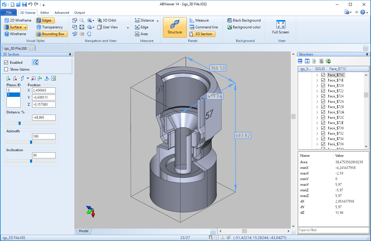
IGES: The Legacy Format That Won’t Retire
File extension: .igs, .iges
Source: CAD Soft tools https://3d-viewers.com/iges-viewer.html
IGES (Initial Graphics Exchange Specification) predates STEP by fourteen years.
Developed in 1980, it was revolutionary for its time and was the first real attempt at CAD interoperability.
The format still appears in older files and legacy systems.
Some organizations have decades of IGES archives, and certain specialized equipment only exports this format.
But for new work, STEP has thoroughly replaced it.
Strengths:
● Supported by virtually every CAD system
● Good for surface geometry and wireframes
● Mature format with predictable behavior
Limitations:
● Solid model support is unreliable
● Often requires geometry repair after import
● No updates since 1996
● Can’t carry modern manufacturing data
Where to view IGES files free:
Viewer | Platform | Notes |
Windows, Mac, Linux | Handles IGES alongside modern formats | |
Web | Quick web viewing | |
Web | Part of Autodesk’s multi-format viewer | |
Windows, Android, iOS | Open CASCADE’s free viewer |
JT: Built for Massive Assemblies
File extension: .jt
Source:http://plm.sw.siemens.com/en-US/plm-components/jt/
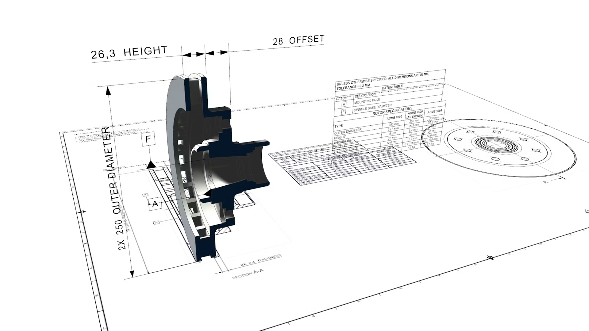
Siemens developed JT specifically for visualizing assemblies too large for normal CAD viewing.
For instance, a full vehicle with every bolt and harness might bring Solidworks to its knees and crash the software.
But JT handles it through intelligent compression and level-of-detail management.
The format stores multiple representations of the same geometry.
There’s a detailed version for close inspection and progressively simplified versions for viewing the overall assembly.
Software automatically switches between them based on the zoom level, and you don’t even notice the effect here!
JT earned ISO standardization (ISO 14306:2017), recognizing its importance in automotive and aerospace supply chains where companies routinely exchange models containing millions of components.
Strengths:
● Exceptional compression for large assemblies
● Multiple detail levels in one file
● Can include precise B-rep geometry or just visualization mesh
● Supports PMI and manufacturing annotations
● Strong in automotive and aerospace industries
Limitations:
● Not as universally supported as STEP
● Primarily a Siemens ecosystem format
● Less useful for small models where compression doesn’t matter
Where to view JT files free:
Viewer | Platform | Notes |
Windows, iOS, Android | Official Siemens viewer, fully featured | |
Web | Handles JT, among many formats | |
Windows (15-day trial) | Professional viewer with free trial period |
3D Printing and Mesh Formats
These formats represent surfaces as meshes instead of line geometries.
These meshes are essentially networks of connected triangles or polygons.
They’re simpler than B-rep (boundary representation) formats and serve visualization, 3D printing, and game development better than precision engineering.
STL: The Original 3D Printing Format
File extension: .stl
Kaboldy, CC BY-SA 3.0 , via Wikimedia Commons
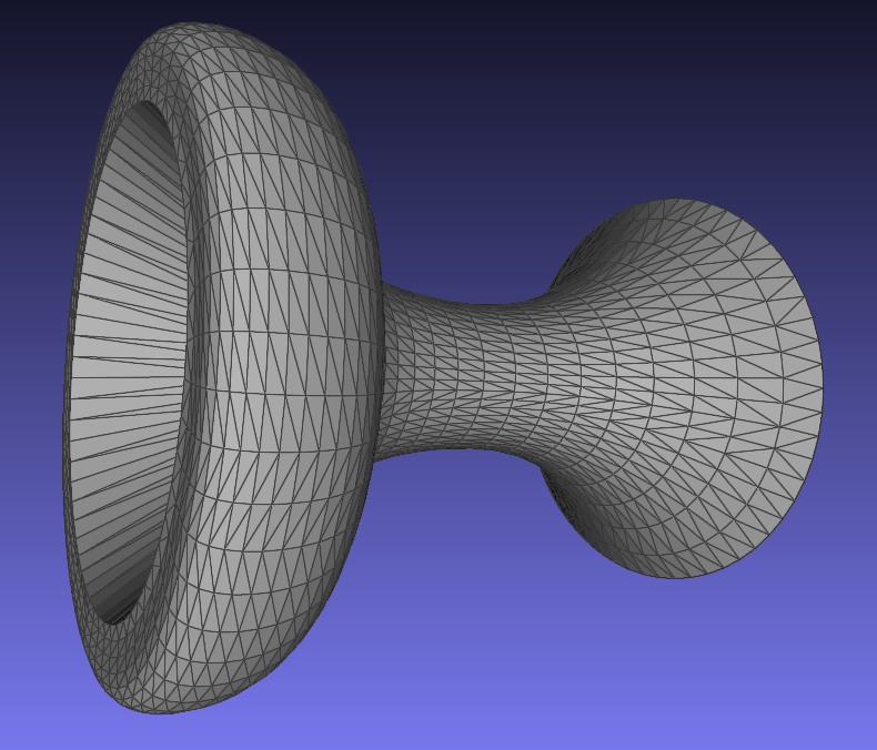
3D Systems invented STL in 1987 for their stereolithography machines.
These were some of the first commercial 3D printers.
The format describes surfaces as collections of triangles, nothing more.
That simplicity became both STL’s greatest strength and its biggest limitation.
Every 3D printer, every slicer software, and every mesh editor supports STL because the format is trivial to implement.
But that simplicity means STL files can’t carry color, texture, material, or unit information.
And for the most part, it works best without any issues.
Strengths:
● Universal 3D printing support
● Extremely simple specification
● The binary version keeps files compact
● Every mesh tool handles it
Limitations:
● No color or texture support
● No unit specification (causes scaling errors)
● Surfaces are approximated, not precise
● Single body only, no assemblies
● No material properties
Where to view STL files free:
Viewer | Platform | Notes |
Web | Single-purpose, extremely fast | |
Windows, Mac, Linux | Professional mesh analysis tools | |
Windows 10/11 | Built into Windows, no install needed | |
Web | Clean interface, measurement tools | |
Windows, Mac, Linux | Full 3D suite, not just viewing | |
Windows 10/11 | Simple built-in option |
3MF: STL’s Modern Replacement
File extension: .3mf
https://apps.autodesk.com/FUSION/de/Detail/Index?id=4108920185261935100&appLang=en&os=Win64
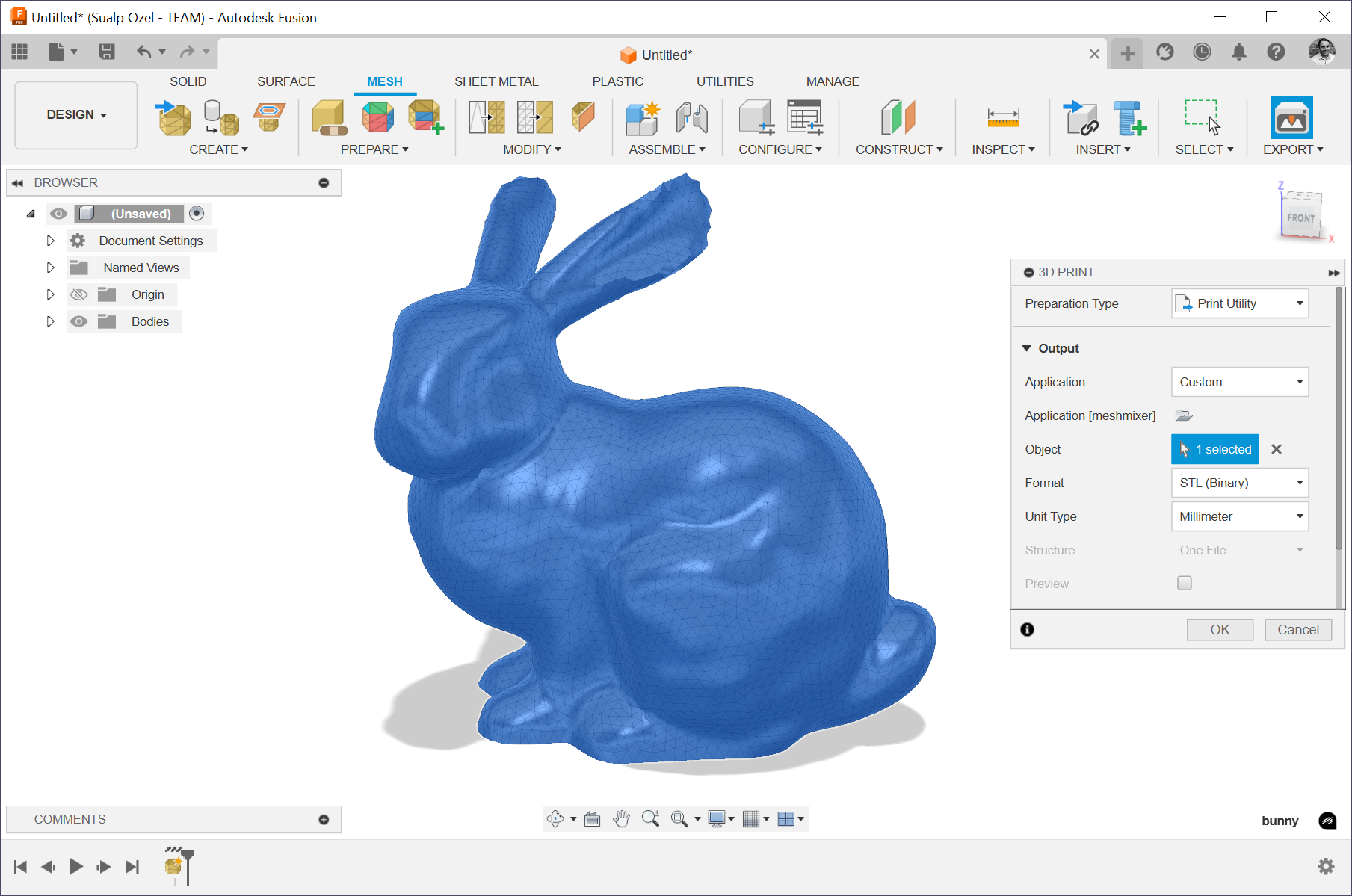
Microsoft, Autodesk, HP, Stratasys, and other industry leaders formed the 3MF Consortium specifically to fix STL’s problems.
The result is a format that does everything STL does while adding the features modern 3D printing needs.
3MF files specify units (no more guessing if dimensions are millimeters or inches), support full-color printing, handle multiple materials, and package everything in a compressed archive.
The format is gaining adoption rapidly, especially with the release of multi-material and full-color printers in recent years.
Strengths:
● Units embedded in the file
● Full color and texture support
● Multiple objects and materials per file
● Compressed for smaller file sizes
● Extensible for future printing technologies
Limitations:
● Not yet universal (though growing quickly)
● Some older printers and slicers don’t support it
● Still mesh-based, not precise geometry
Where to view 3MF files free:
Viewer | Platform | Notes |
Windows 10/11 | Native Windows support | |
Windows 10/11 | Built-in, simple viewing | |
Web | Multi-format web viewer | |
Windows, Mac, Linux | Slicer software that previews 3MF | |
Windows, Mac, Linux | Popular slicer with 3MF support |
OBJ: The Bridge Between CAD and Creative Software
File extension: .obj
https://fileinfo.com/extension/obj
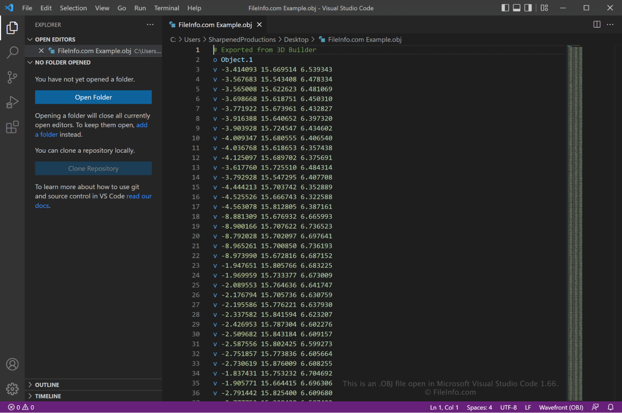
Wavefront Technologies created OBJ for their animation software in the 1980s.
The format became a standard bridge between engineering CAD and creative applications like game engines, rendering software, and animation tools.
Unlike STL, OBJ supports texture coordinates, vertex colors, and smooth shading through vertex normals.
A companion .mtl file defines materials and can reference texture images.
Where to view OBJ files free:
Viewer | Platform | Notes |
Windows, Mac, Linux | Industry-standard 3D software | |
Windows, Mac, Linux | Mesh processing and viewing | |
Windows 10/11 | Built-in Windows viewer | |
Web | Quick web-based viewing | |
Web | Shows textures if MTL file included |
glTF: The Web’s 3D Format
File extension: .gltf, .glb
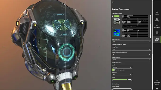
The Khronos Group (the same organization behind OpenGL and Vulkan) designed glTF specifically for transmitting 3D content over the web and to real-time applications.
It’s often called the “JPEG of 3D” because it’s optimized for size and loading speed
The format supports physically based rendering (PBR) materials, skeletal animation, and morph targets.
The binary .glb variant packs everything—geometry, textures, animations, etc.—into a single file.
Strengths:
● Optimized for web delivery
● Excellent real-time rendering support
● PBR materials for realistic appearance
● Animation and skinning support
● Single-file binary option
Limitations:
● Not for precision engineering work
● Limited CAD software support
● Primarily visualization, not manufacturing
Where to view glTF files free:
Viewer | Platform | Notes |
Web | Reference viewer from format contributor | |
Web | Microsoft’s 3D engine viewer | |
Web | Popular WebGL library’s viewer | |
Windows 10/11 | Native Windows support | |
Windows 10/11 | Full import/export support |
Native CAD Formats: Major Platforms
Each CAD software has proprietary file formats optimized for its specific features.
These formats preserve parametric relationships, feature history, custom properties, and other specific things the software has to offer.
However, they come at a cost—you need the parent software or compatible viewers to access and view the files.
SolidWorks
Extensions: .sldprt (part), .sldasm (assembly), .slddrw (drawing)
Browerz, CC BY-SA 4.0 , via Wikimedia Commons
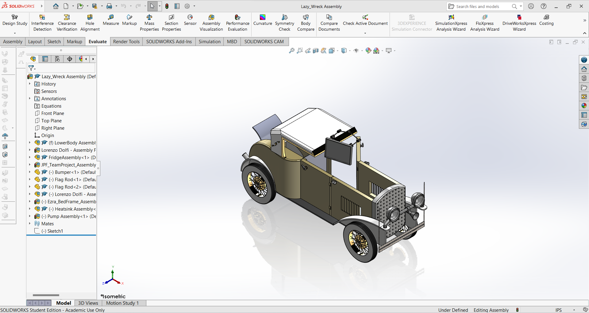
Dassault Systèmes’ SolidWorks dominates the mechanical CAD software base.
CSWA certification or CSWP certification, understanding SolidWorks file formats is essential for exam success.
Its files contain complete feature trees, configurations, and custom properties.
Where to view SolidWorks files free:
Viewer | Platform | Notes |
Windows, Mac, iOS, Android | Official Dassault viewer | |
Web | Good compatibility | |
Windows (trial) | Shows feature tree | |
Windows (limited free) | Includes analysis tools |
CATIA
Extensions: .CATPart (part), .CATProduct (assembly), .CATDrawing (drawing)
Smashing.cadillac, CC BY-SA 3.0 , via Wikimedia Commons
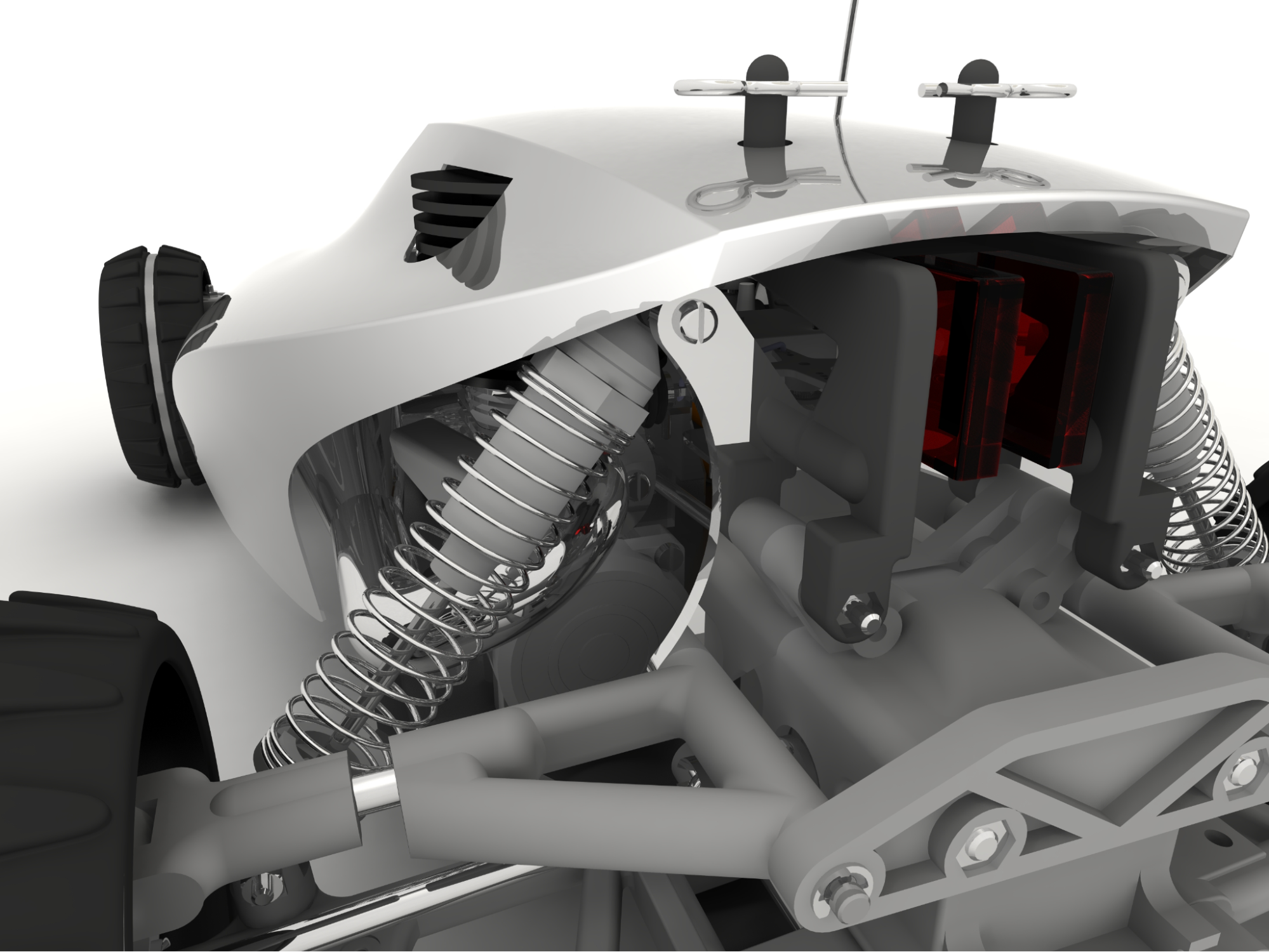
CATIA leads in aerospace and automotive, where complex surface modeling and massive assemblies are standard.
The format handles Class A surfaces and advanced simulation data with ease.
Where to view CATIA files free:
Viewer | Platform | Notes |
Windows | Official Dassault viewer (requires 3DXML export) | |
Windows (trial) | Direct CATPart viewing | |
Web | Basic geometry viewing |
PTC Creo (Pro/ENGINEER)
Extensions: .prt (part), .asm (assembly), .drw (drawing)
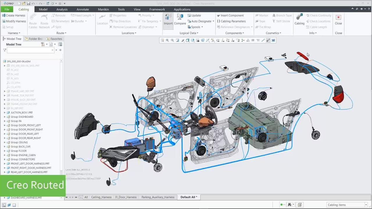
https://www.ptc.com/en/products/creo/parametric
Creo has deep roots in mechanical engineering and remains strong in consumer products and industrial equipment design.
Where to view Creo files free:
Viewer | Platform | Notes |
Windows | Official PTC viewer | |
Windows (trial) | Good Creo support | |
Web | Basic viewing capability |
Autodesk Inventor
Extensions: .ipt (part), .iam (assembly), .idw (drawing)
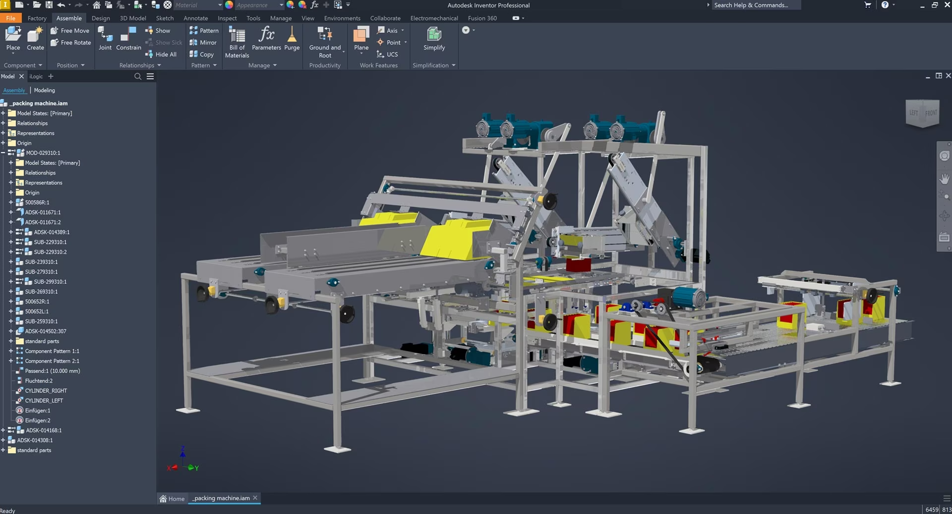
https://www.autodesk.com/products/inventor/features
Inventor is Autodesk’s answer to SolidWorks, popular for product design and mechanical engineering, especially in shops already using AutoCAD.
Where to view Inventor files free:
Viewer | Platform | Notes |
Web | Official viewer, excellent support | |
Windows (trial) | Full feature access | |
Web | Autodesk cloud platform |
Solid Edge
Extensions: .par (part), .asm (assembly), .dft (drawing)
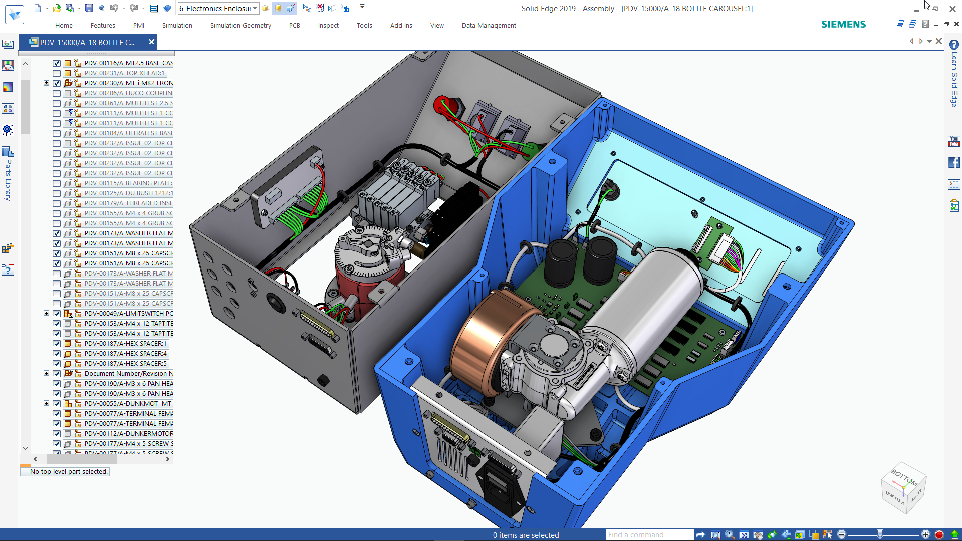
https://solidedge.siemens.com/en/free-software/overview/
Siemens’ Solid Edge combines traditional parametric modeling with synchronous technology for flexible direct editing.
Where to view Solid Edge files free:
Viewer | Platform | Notes |
Windows, iOS, Android | Siemens official viewer | |
Windows (trial) | Direct format support |
Fusion 360
Extension: .f3d (archive), .f3z (with references)
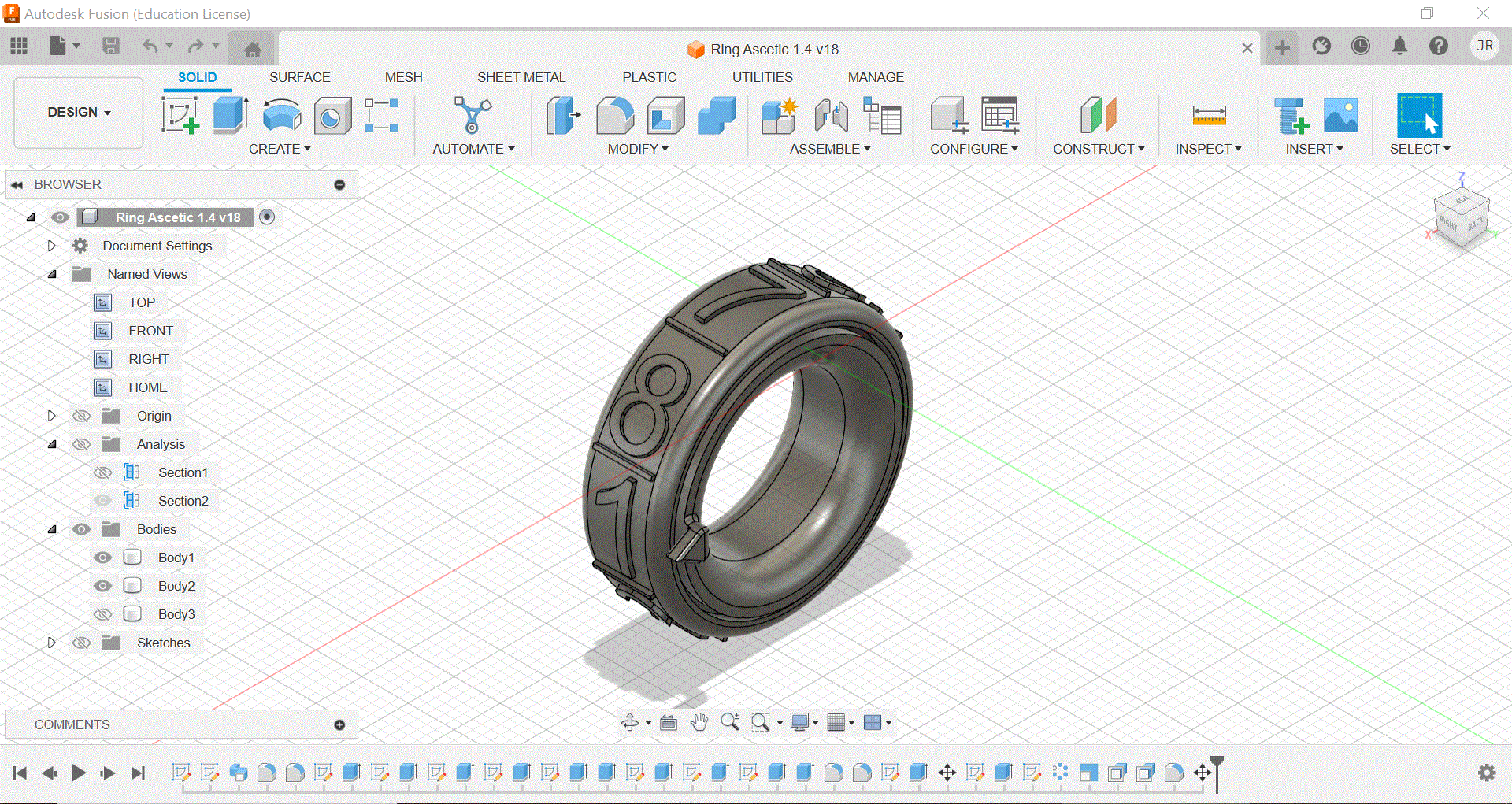
Parzival73, CC BY-SA 4.0 , via Wikimedia Commons
Autodesk’s cloud-native Fusion 360 stores files primarily in the cloud, though you can export local archives.
Where to view Fusion files free:
Viewer | Platform | Notes |
Fusion 360 Free | Windows, Mac | Free for personal use |
Autodesk Viewer | Web | Upload exported files |
Rhino
Extension: .3dm
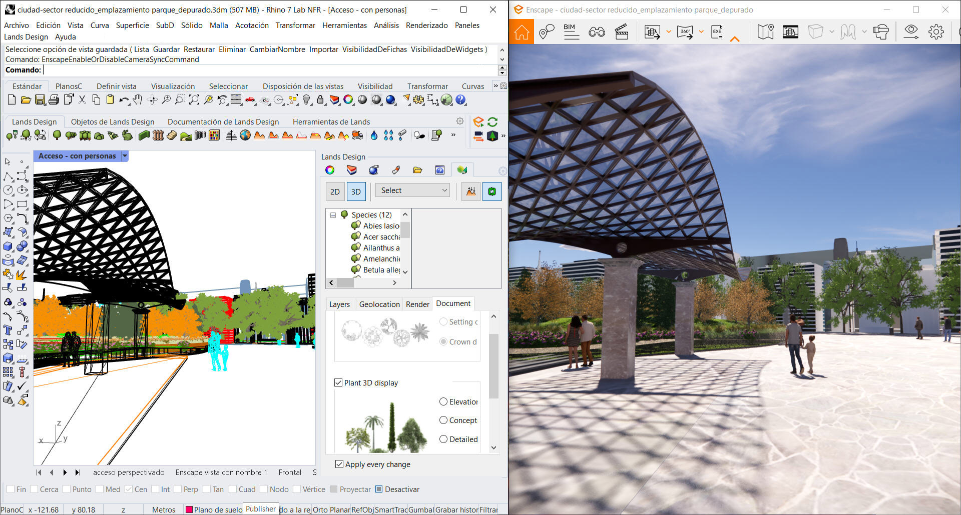
https://www.rhino3d.com/en/for/landscape-design/
Rhino excels at freeform surface modeling, making it popular in industrial design, jewelry, and architecture.
Where to view Rhino files free:
Viewer | Platform | Notes |
Rhino 3D Viewer | iOS | Official mobile viewer |
ShareCAD | Web | 3DM support |
Autodesk Viewer | Web | Basic geometry viewing |
Quick Reference: Format Selection Guide
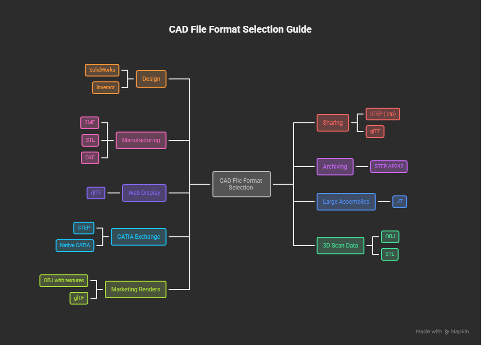
Now here is a use case as well as the format type that supports that use case in a proper table format as well as in a flowchart format.
You need to.. | Use this format |
Work on your design | Native format (SolidWorks, Inventor, etc.) |
Share with unknown CAD software | STEP (.stp) |
Send to a 3D printer | 3MF (preferred) or STL |
Send to laser cutter/CNC router | DXF |
Archive for long-term storage | STEP AP242 |
Display on a website | glTF |
Share huge assemblies for review | JT |
Exchange with CATIA users | STEP or native CATIA |
Import 3D scan data | OBJ or STL |
Create marketing renders | OBJ with textures or glTF |
Avoiding Common Problems
When sharing files using any of these file formats, you may end up with some common problems that I’ve listed below.
Check it if any of these issues look familiar.

Missing units in STL files:
Always confirm the unit system you’re using before exporting the STL.
Most slicers assume millimeters by default.
So, sometimes a model designed in inches will print 25.4 times smaller than intended if your units aren’t sent correctly.
STEP files with broken geometry:
Some CAD translations produce self-intersecting surfaces or gaps.
Run geometry checks after importing the STEP files, and heal errors before using the model.
Lost assembly structure:
Basic STEP exports flatten assemblies into single bodies.
Use the STEP AP214 or AP242 file formats with assembly structure enabled to preserve the hierarchy of your models.
Colors not transferring:
STL and basic STEP file formats don’t carry color.
Use 3MF, OBJ with material, or JT for colored visualization of your 3D files.
Features tree missing:
You won’t get the parametric features in any neutral format.
Always keep the native files as the master copies, and export neutral formats only for sharing purposes!
Complete Roundup: Free CAD Viewers
To make things easier for you, here are some of the most versatile free CAD viewers that handle multiple file formats.
Autodesk Viewer (Web) Formats:
DWG, DXF, DWF, RVT, IPT, IAM, STEP, IGES, OBJ, STL, CATIA, SolidWorks, and 80+ more.
It is best for quick viewing without installing software.
FreeCAD (Desktop) Formats:
STEP, IGES, OBJ, STL, DXF, DAE, and many more.
It is best for viewing plus actual CAD editing when needed.
Glovius (Desktop, 15-day trial) Formats:
Nearly all major native and neutral formats.
It is best for professional viewing with measurement and section tools.
ShareCAD (Web) Formats:
DWG, DXF, STEP, IGES, STL, Parasolid, ACIS, and more.
It is best for sign up free instant viewing of CAD files.
MeshLab (Desktop) Formats:
STL, OBJ, PLY, 3DS, and 30+ mesh formats.
It is best for mesh analysis and repair.
Blender (Desktop) Formats:
OBJ, STL, glTF, FBX, DAE, 3DS, and more.
It is best for visualization and rendering.
Summary
It’s easy to overlook the importance of CAD file formats. Why would anyone give it a thought anyway until you’re stuck with an unopenable file or a model that’s imported as a mess of broken surfaces?
Understanding the strengths and trade-offs of each format helps you make better decisions about your CAD workflow.
Your original works should remain in native formats where you have full editing capabilities. Export to STEP for professional CAD exchange, 3MF or STL for 3D printing, and DXF for 2D fabrication.
Have a CAD format question we didn’t cover? Working with an unusual file type? Drop your questions in the comments below.