Engineering Line Types: A Complete Guide for Technical Drawing
Technical drawings are a universal language in engineering. But that language is incomplete without one critical element: line types. Every line you see on…
Technical drawings are a universal language in engineering.
But that language is incomplete without one critical element: line types.
Every line you see on an engineering drawing carries a specific meaning.
A dashed line indicates a hidden edge.
A line with alternating long and short dashes marks a center point.
These distinctions, the subtle gaps, and the patterns all communicate critical manufacturing and construction information.
In case you use a solid line in place of dashes or a wrong line weight…well, that can lead to flawed parts in manufacturing! Understanding these line types will help you prevent costly mistakes.
This guide will walk you through the standards that dictate line types, the various patterns you’ll come across, and the correct way to use them within your CAD software.
Let’s sketch it out.
Understanding Line Type Standards
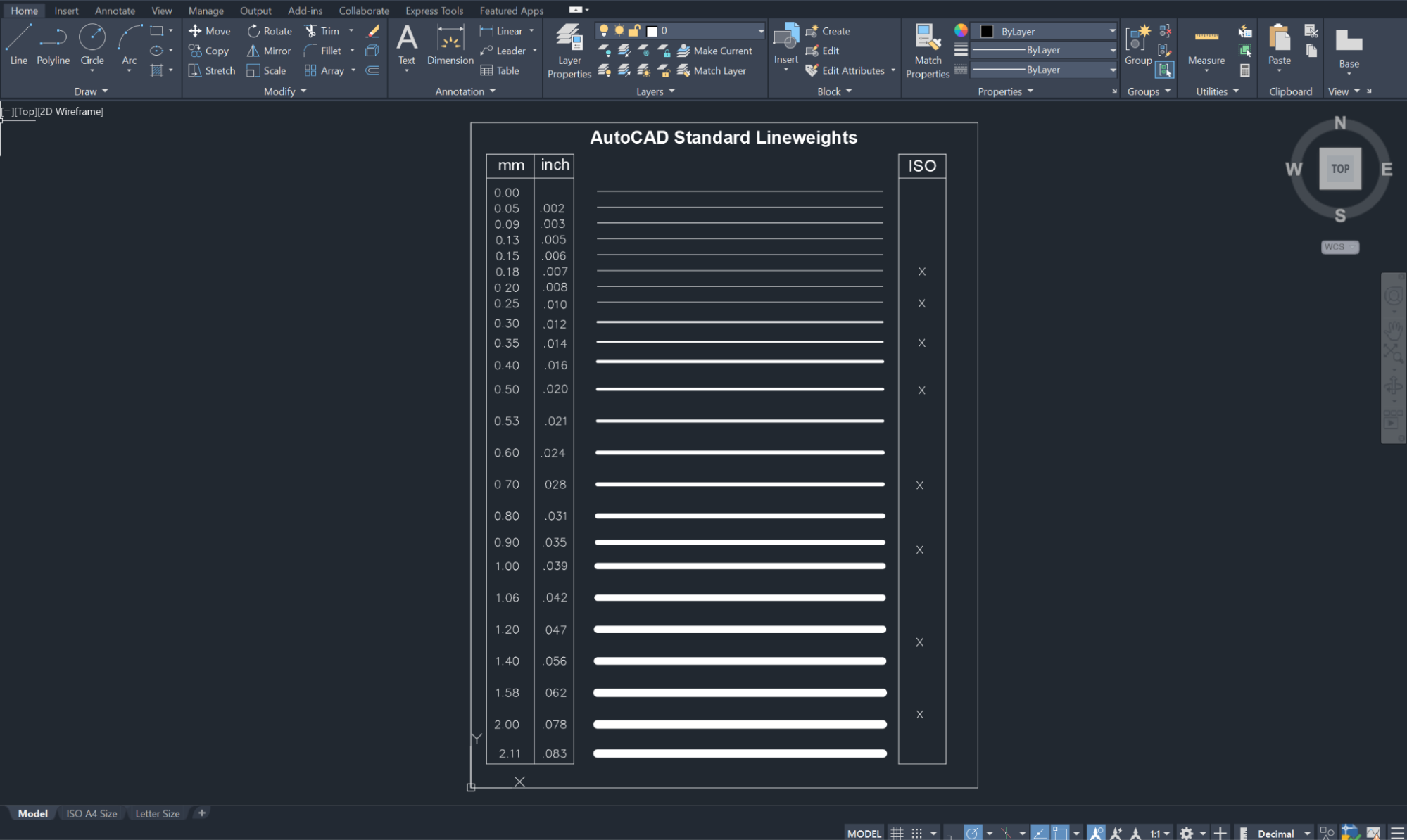
There are two main standards governing engineering line types worldwide.
ASME Y14.2 (Line Conventions and Lettering) applies in North America, while ISO 128 serves as the international standard.
Both of these standards define the same core principles: specific meanings for each line type, standardized thicknesses, and distinctive patterns.
The standards typically define two primary line weights: thick lines at 0.6 mm and thin lines at 0.3 mm. This 2:1 ratio ensures a clear visual hierarchy.
You use thick lines to show important information, like visible edges, and thin lines to show less important information, like dimensions and hidden features.
When you combine the line weight with a specific pattern, you create distinct visual signatures that remain recognizable regardless of the drawing’s scale or who created it.
The pattern in this case refers to whether a line is continuous, dashed, or with alternating segments.
Essential Line Types in Engineering Drawing
Here are fundamental line types you will encounter in technical drawings, along with their characteristics and applications.
Visible Lines: Defining Object Shape
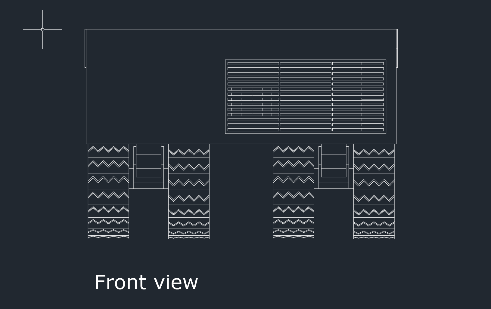
Visible lines are thick, 0.6 mm continuous solid lines.
You use them to show the edges and outlines that are directly visible from your current viewpoint.
When you draw a part in the front view, visible lines outline all the outer edges, surface limits, and features that someone would see from that specific angle.
These lines are the thickest because of how we humans process visual information.
Our eyes naturally gravitate toward the darkest and most prominent marks first.
The thick, visible lines help us quickly understand the object’s basic shape.
All the other elements in the drawing simply support and add detail to these main outlines.
Hidden Lines: Showing Obscured Features
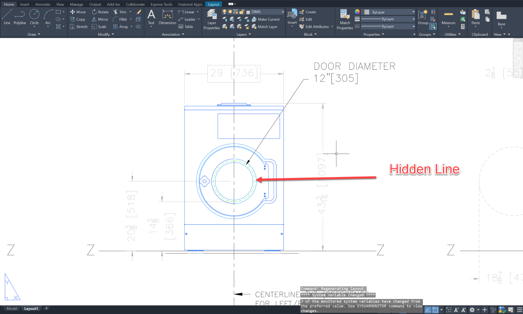
Hidden lines in drawings are thin, 0.3 mm, and with short and evenly spaced dashes.
These lines show edges and features that physically exist but aren’t visible from the current view because other parts obscure them.
Imagine a rectangular block with a cylindrical hole drilled completely through it from top to bottom.
When you draw this block from the front view, you can’t see the hole directly.
A hidden line will show exactly where that hole is and communicate its presence behind the visible surface.
The visual pattern follows specific drafting conventions.
Each hidden line should start and end with a dash rather than a gap.
When hidden lines form corners, the dashes there need to meet clearly without any gaps interrupting the junction.
While hidden lines are great for showing simple internal features, you should avoid using them excessively.
If the internal geometry becomes too complex, it is much better to use a section view rather than cluttering your sheet with masses of dashed lines.
Center Lines: Locating Circular Features
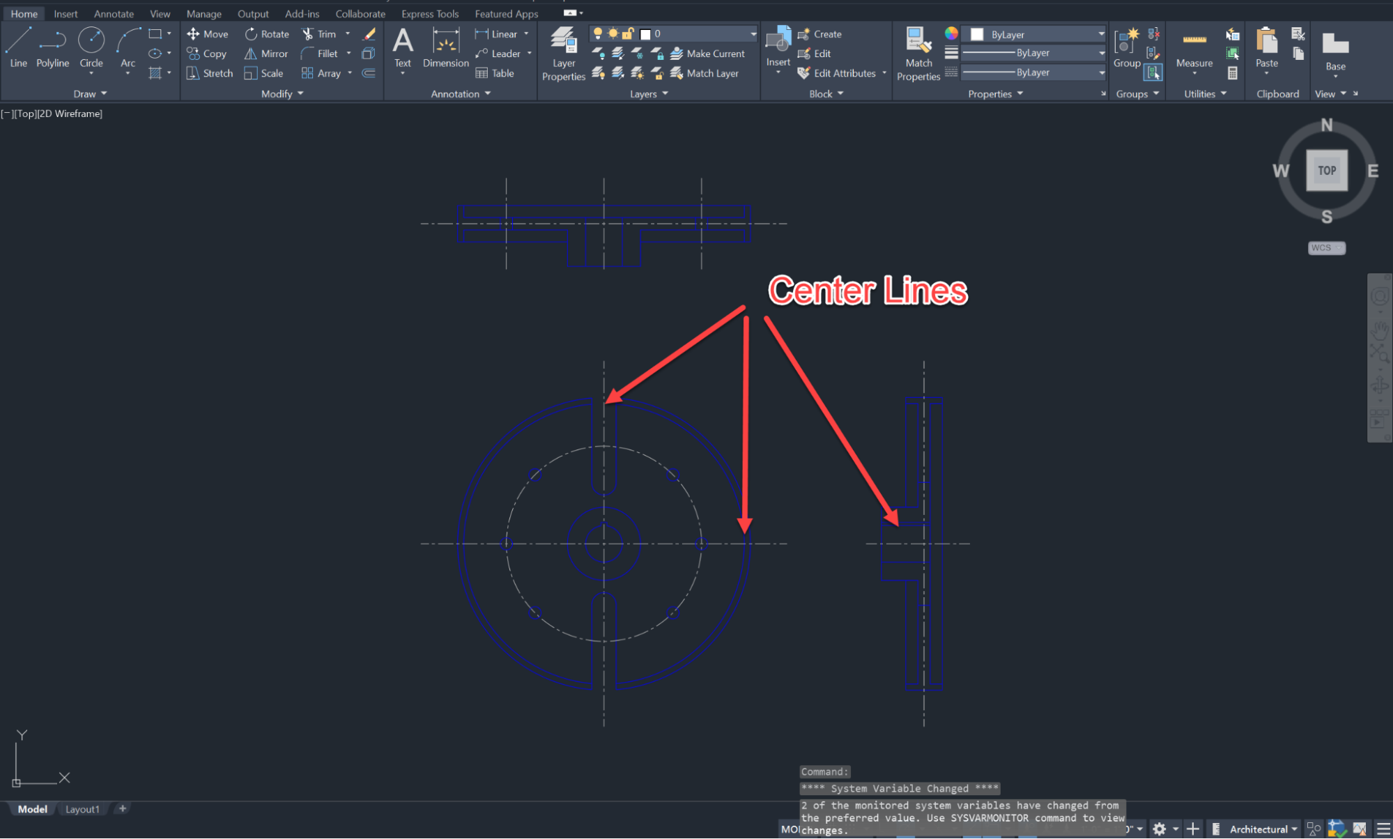
Center lines are thin (0.3 mm) with alternating long and short dashes.
You use these to mark the centers of circles, arcs, and symmetrical features.
The line extends slightly beyond the circular feature it marks.
The importance of center lines relates entirely to how we dimension circular geometry.
When you need to specify where to drill a hole, you are actually specifying the location of the hole’s center point.
Without a centerline marking that exact center, you have no clear reference point for your dimension.
When two center lines intersect, they should, ideally, cross at their long dashes or both at the short dashes to maintain visual consistency.
You’ll notice the mechanical engineering drawings use center lines extensively.
On the other hand, you will see fewer center lines in architectural drawings.
Here, too, they’re used to mainly mark the circular elements like columns.
Dimension and Extension Lines: Communicating Size
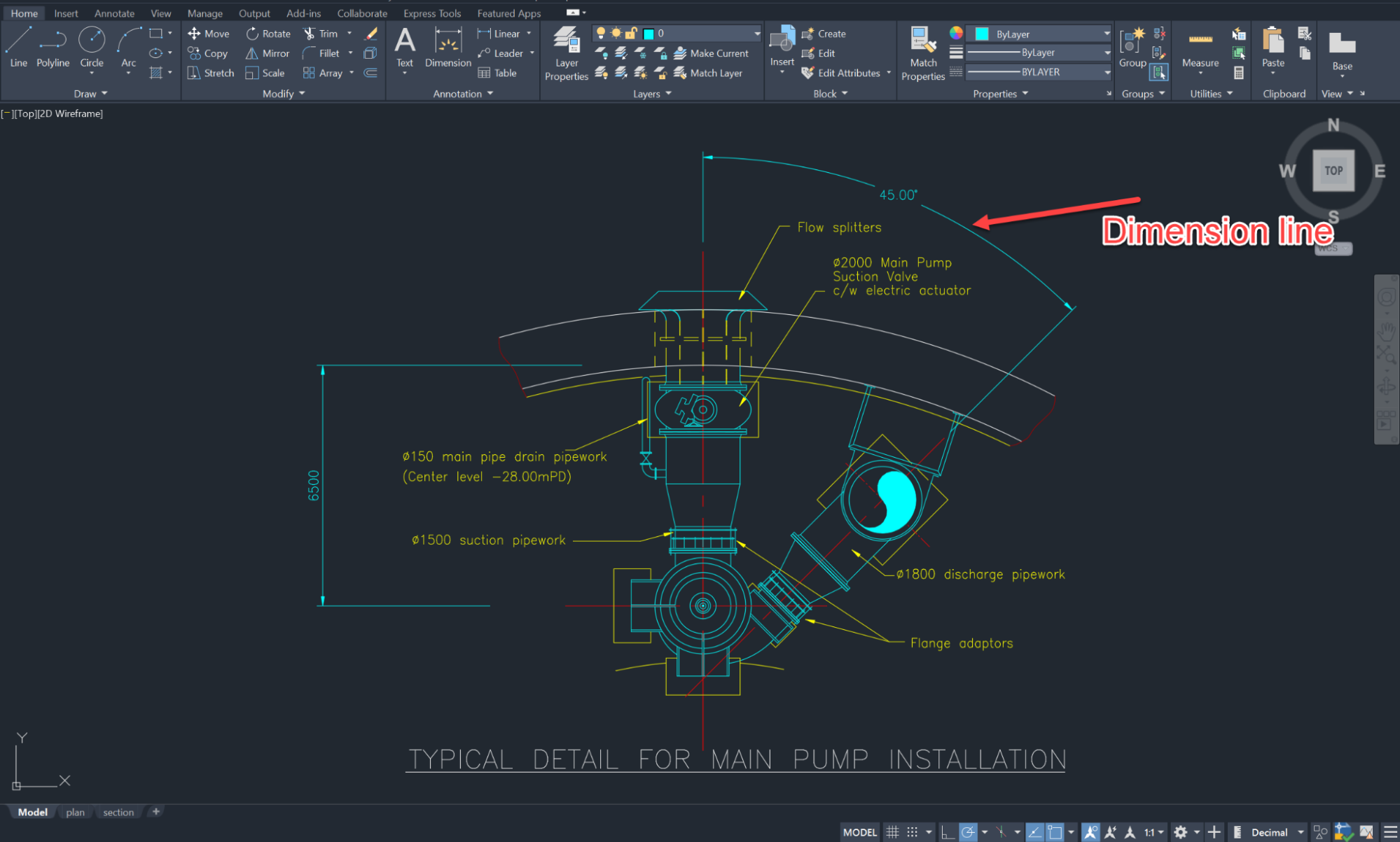
Dimension lines and extension lines are both thin (0.3 mm) continuous lines, but they serve different purposes.
● Dimension lines span between two points to show a measurement in drawings.
They end in arrowheads at each side and usually break in the middle to contain the numerical dimension value.
● Extension lines project outward from the object to define exactly where those dimensions start and end.
Extension lines should never touch the object directly.
You typically leave a small gap of about 1.5 mm between the extension line and the object’s edge.
This gap helps prevent anyone from confusing the extension line with the object’s actual physical edges.
Both of these lines use the thin weight because they describe and measure the object, rather than defining its shape.
Section Lines: Indicating Cut Surfaces
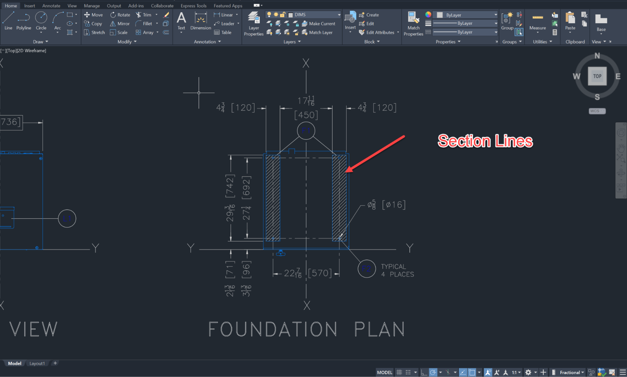
Section lines, sometimes called hatch lines, solve the problem of showing what’s inside an object.
These thin (0.3 mm) continuous lines typically angle at 45 degrees and fill the areas that you have cut in a sectional view.
The concept works like slicing through an object with an imaginary cutting plane and then removing one portion to reveal what’s inside.
You fill the surface you’ve cut through with section lines, making it immediately recognizable as a cut solid.
Without them, readers would struggle to understand what’s being cut versus what’s sitting in the background.
Different hatching patterns can represent different materials, though their usage varies between industries.
In mechanical drawings, steel might use one pattern while aluminum uses another.
When a section cuts through an assembly of multiple parts, changing the hatching angles for adjacent parts helps readers distinguish one component from another.
Cutting Plane Lines: Showing Where You Cut
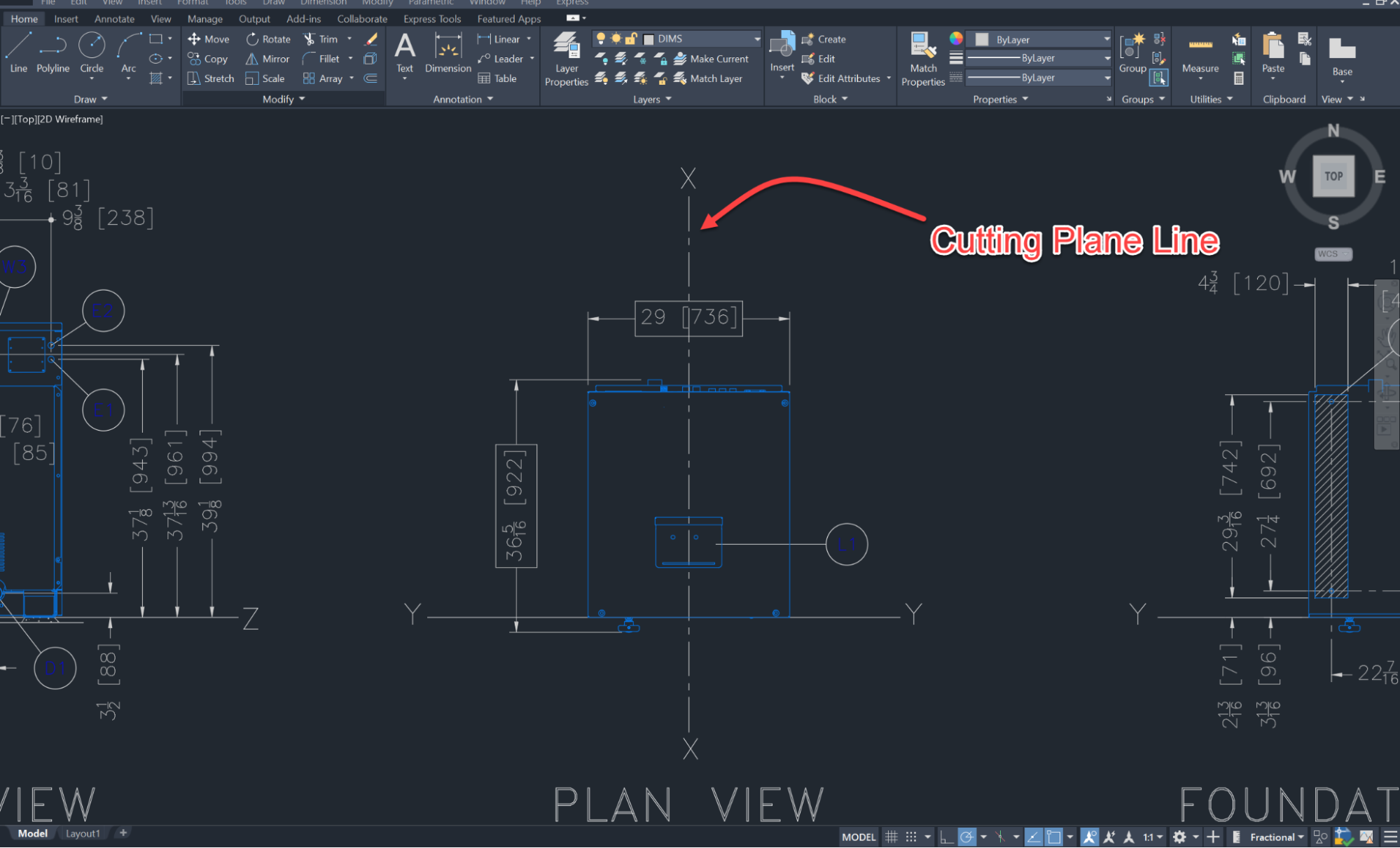
Cutting plane lines are thick (0.6 mm) lines with alternating long and short dashes.
These work directly with section views to show exactly where you positioned that imaginary cutting plane.
They appear in one view and point to the corresponding section view elsewhere on the sheet.
The line terminates with arrowheads, which are highly useful because they indicate the exact direction you are looking at the cut.
You use letters to identify the cutting plane and its corresponding section.
For instance, you might see a cutting plane labeled “A-A” in the top view and then find the actual section view labeled “SECTION A-A” elsewhere.
Phantom Lines: Showing Alternate Positions and Adjacent Parts
Phantom lines follow a distinctive pattern with one long dash, followed by two short dashes.
And depending on the drawings’ context, they serve different purposes!
Their most common application is showing the alternate positions of moving parts.
For instance, when you draw a hinged door, phantom lines help you show the door in both its open and closed positions within a single view.
You can also use phantom lines to indicate adjacent parts that aren’t a part of the current drawing but still provide important context.
A third use of phantom lines involves showing repeated features in your model.
If your design includes a pattern of identical features, you can draw one or two features completely and then use phantom lines to indicate where the pattern continues.
Break Lines: Shortening Long Objects
https://graphicdesign.stackexchange.com/questions/45929/what-is-this-design-pattern-called-continuation-wave
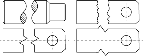
Break lines let you show long objects at a readable scale without dedicating an entire sheet just to fit their full length.
These come in three varieties for different situations:
● Short break lines: Thick (0.6 mm) freehand wavy lines for breaking the edges of flat objects.
● Long break lines: Thin (0.3 mm) straight lines with periodic zigzag sections for longer breaks.
● Cylindrical break lines: Thin (0.3 mm), curved, irregular lines that perfectly represent cylindrical forms, such as shafts or pipes.
Break lines save space when you draw long objects that have consistent cross-sections.
Instead of drawing a 10-foot beam at a tiny scale, you can show both ends at a readable scale and simply use break lines to indicate that you omitted the middle section.
Border Lines: Framing Your Drawing
rhesusminus via Autodek Forumshttps://forums.autodesk.com/t5/autocad-electrical-forum/drawing-template-and-border-alphanumeric-number-references/td-p/6593716?lightbox-message-images-6593983=277627iE407DE542AA82456
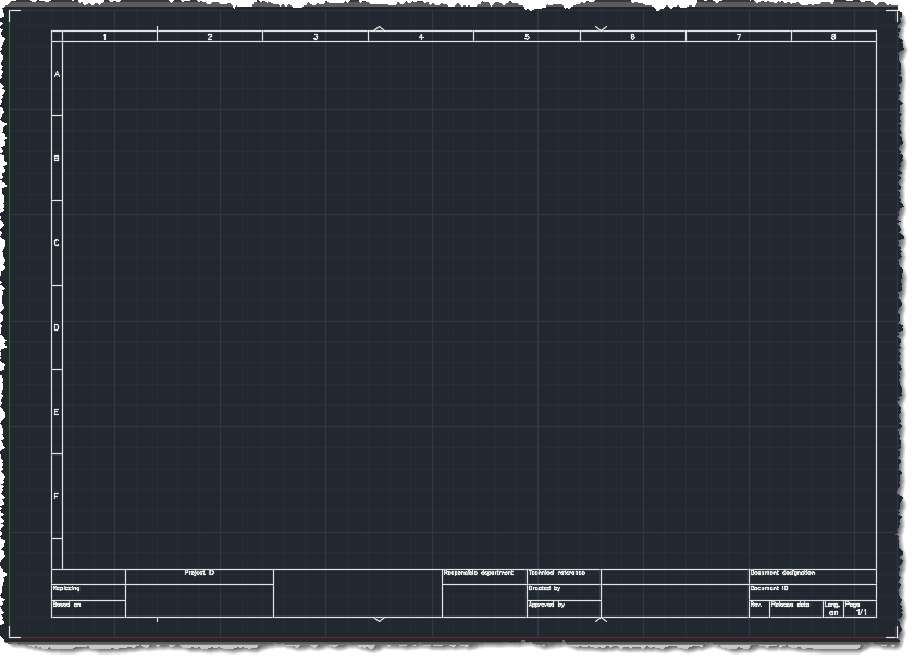
The thick (0.6 mm) border lines help you frame your engineering drawing properly.
These lines define the boundary of the drawing area and separate the working space from the title block.
Getting a drawing set up right from the start is super important for consistent documentation.
That means taking the time to nail down the basics like borders, title blocks, and standard text sizes right away.
Line Types Across Engineering Disciplines
Different engineering disciplines emphasize different line types based on what they typically need to communicate.
Mechanical engineering drawings use the complete range regularly.
Complex internal features mean a heavy use of hidden lines, as well as section view
s with cutting plane lines.
Center lines are also absolutely critical because of the high volume of cylindrical parts, holes, and rotating assemblies.
Architectural drawings rely heavily on visible lines and use hidden lines sparingly.
Phantom lines are common for furniture layouts and equipment positions.
The emphasis here is on clarity and readability at scales that show entire buildings.
Civil engineering drawings adapt line types for infrastructure and site work.
Here, phantom lines might indicate underground utilities or alternate property boundary positions.
There are also specialized line types for fencing boundaries and utilities, which are specific strictly to civil work.
Implementing Line Types in AutoCAD
AutoCAD controls line types through its layers and object properties.
The ByLayer approach is the best practice: you assign line types to layers rather than individual objects.
When you draw on a layer, your geometry automatically adopts that layer’s assigned line type, color, and line weight.
Loading Line Types
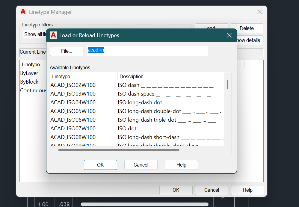
Type LT in the command line to open the Linetype Manager.
Click Load to access the acad.lin file (or acadiso.lin for metric users).
This file contains all the standard linetypes.
You simply select the ones you need and load them into your current drawing.
Understanding Line Type Scaling
Line type scaling can easily cause the most confusion in AutoCAD.
There are four system variables that control how line types display in the software:
● LTSCALE: This is the global linetype scale that affects all linetypes in the drawing.
Set this to 1 for paper space layouts. If your dashed lines appear solid, increase your LTSCALE.
If the dashes are too large, decrease it.
● MSLTSCALE: This controls whether the annotation scale affects linetypes in model space.
Set this to 1 for proper scaling based on your chosen annotation scale.
● PSLTSCALE: This controls linetype scaling within paper space viewports.
Set this to 1 to maintain a consistent appearance across different viewport scales.
● CELTSCALE: This controls the linetype scale for the new objects you create.
Keep this at 1 and let LTSCALE handle your global scaling.
If all your line types look correct in model space but display poorly in paper space (or vice versa), check your PSLTSCALE and MSLTSCALE settings.
Setting Up Templates in AutoCAD
Setting up line types in a template file helps you eliminate repetitive work and ensures total consistency across your drawings.
Your template should include standard layers with appropriate line types assigned to them, along with your dimension styles and text styles.
Advanced CAD Tools for Line Type Management
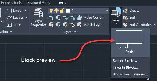
Using AutoCAD blocks will help you save time when creating repeated elements with specific line types.
Blocks maintain their assigned properties and can be inserted multiple times while preserving the correct line-type assignments.
The annotation scale system in AutoCAD is another one of the useful tools.
It helps you maintain consistent line types across different drawing scales.
When you work with multiple views at different scales, the annotation scale ensures your dashes and gaps remain readable and visually consistent.
Line Types in Other CAD Software
Revit handles line types through patterns assigned to line styles.
You can access these through additional settings under the line pattern menu.
The approach is parallel to AutoCAD’s layer-based system but is streamlined for architectural work.
SolidWorks and other parametric modelers control line types through layer properties and line font settings in their drawing views.
While the exact terminology might vary between programs, the underlying concepts of line types remain completely consistent.
Best Practices for Line Type Usage
Follow Line Precedence.
When lines overlap in a drawing, a strict hierarchy exists to determine which one appears on top:
1. Visible lines (Top priority)
2. Hidden lines
3. Cutting plane lines
4. Centre lines
5. Dimension/extension lines (Lowest priority)
Following this hierarchy prevents cluttered drawings and keeps your sheets clean and readable.
Maintain Consistent Line Weights When you define thin lines as 0.3 mm, that definition must apply throughout the entire drawing.
This consistency lets everyone instantly distinguish line types based on their weights alone.
Arbitrarily mixing up line weights will destroy your drawing’s visual hierarchy.
Use Section Views Instead of Excessive Hidden Lines.
Don’t fill your drawings with dashed lines trying to show every single internal feature.
The result is just a cluttered mess of lines that will be incredibly hard to read.
Instead, if you find yourself drawing too many hidden lines, ask yourself whether a section view would make the geometry clearer.
Always Check Printed Output Line types that look perfect on a screen can appear vastly different when you print them out.
Always plot a test print before finalizing anything.
Check the output, adjust your LTSCALE or line weights if needed, and print again.
This step is especially critical for manufacturing or construction submittals.
Mastering Line Types
Line types form the core vocabulary of your engineering drawing.
When you understand them thoroughly, you can read any engineering drawing and extract the exact information it contains.
More importantly, you can create drawings that communicate clearly to manufacturers, builders, and other engineers.
The standards governing line types might seem rigid and detailed at first.
However, these standards exist because they actually work. When everyone follows the same conventions, ambiguity disappears, and costly errors decrease.
A centerline marks a center point with the exact same meaning whether you are designing a medical device or a piece of heavy industrial machinery.
Start by learning the basic line types and their meanings first, and practice identifying them in professional drawings.
Then, set up your CAD templates correctly so your software handles the technical display details while you focus entirely on the design.
If you have any questions about line types or issues with CAD software display.