How to Create Threads in SolidWorks 3 Methods Best Practices
Since its inception in 1995, SolidWorks has been the go-to software for mechanical designers and engineers in general. Its thread creation, however, still…
Since its inception in 1995, SolidWorks has been the go-to software for mechanical designers and engineers in general.
Its thread creation, however, still remains a challenge, a trick, and a query for many.
In my time with SolidWorks, I have seen people spend far too much time trying to model the perfect threads when a simple cosmetic thread annotation would suffice.
On the other hand, I’ve seen people struggle with 3D printing models with cosmetic threads and wonder why the threads won’t show up in the slicer software.
This guide discusses all the methods you can use to create threads in Solidworks.
We dive into understanding when to use each one and how to actually do it.
Let’s thread in!
Why Thread Selection Matters
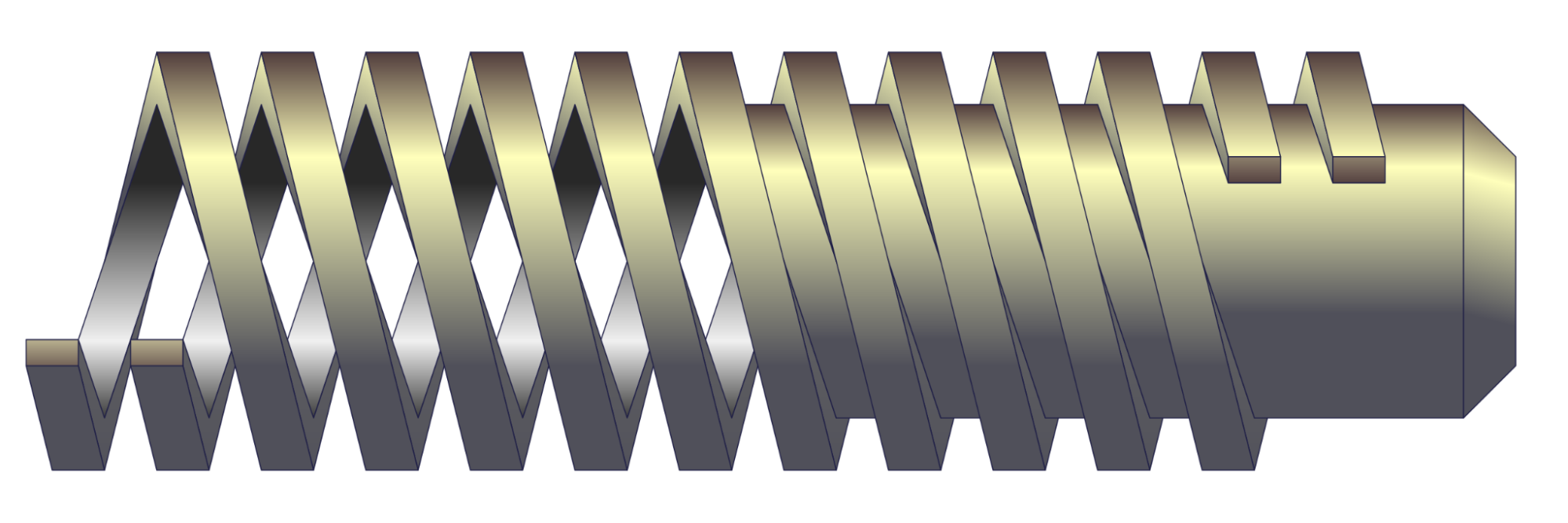
By Browerz – Own work, CC BY-SA 4.0, https://commons.wikimedia.org/w/index.php?curid=130673475
Let’s hold your threads and understand first the trade-offs between different methods of creating threads in Solidworks.
Threads are resource intensive and demand computing power from your system.
A simple cosmetic thread takes approximately 0.02 seconds to rebuild.
The built-in thread feature takes approximately 0.5 to 1 second.
And finally, a manually modeled thread with helix and sweep can take anywhere between 10 to 20 seconds or even longer depending on the complexity of the design.
It doesn’t look like much, but now multiply this one resource by dozens of threaded holes in an assembly, and you can understand why Solidworks will keep crashing out on you.
The rule is straightforward: choose the simplest method to complete the task.
And select the thread based on your task.
Method 1: Cosmetic Threads (Fast and Light)
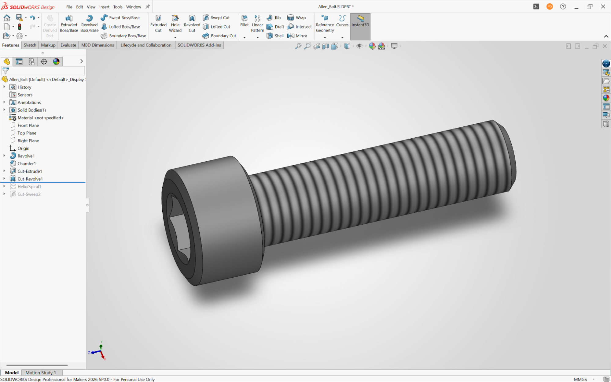
Cosmetic threads are merely annotations that indicate where threads exist without modeling the geometry of the thread.
They’re essentially just visual markers that appear on the SolidWorks drawings and in your model tree.
They don’t actually cut into the shaft, just give the appearance of it.
And they’re ideal, I’d say, for most of your design projects.
When To Use Cosmetic Threads
As per our above rule, remember the task you’re using the cosmetic threads for.
You should use cosmetic threads when you are:
● Developing documentation and drawings
● Working in large assemblies where performance is critical.
● Designing parts with threads that will be cut or tapped later during manufacturing.
● Using standard fasteners that do not require detailed modeling.
Avoid using cosmetic threads when 3D printing functional parts.
They simply just won’t export.
Also skip these threads when you require accurate thread geometry for analysis or machining your models.
How to Create a Cosmetic Thread
You can create cosmetic threads using the Hole Wizard. This method is recommended for holes.
1. Start the Hole Wizard: Go to Insert > Features > Hole > Wizard.
2. Select “Cosmetic Thread”: In the settings panel, click the middle icon.
3. Define the Thread: Choose your thread standard (like UNC or metric), the size, and how deep the thread goes (end condition).
4. SolidWorks will create the hole and the thread annotation automatically.
Adding a Cosmetic Thread to an Existing Feature (Hole or Shaft)
1. Select the Edge: Click on the circular edge where the thread should start.
2. Add the Annotation: Go to Insert > Annotations > Cosmetic Thread.
3. Define the Thread: Specify the thread type, size, and depth.
You should remember, that cosmetic threads are simply annotations in SolidWorks.
The thread information disappears when you export the file in STL for 3D printing.
The threads also won’t be visible if someone else removes the the annotation from your models.
Making Cosmetic Threads Visible
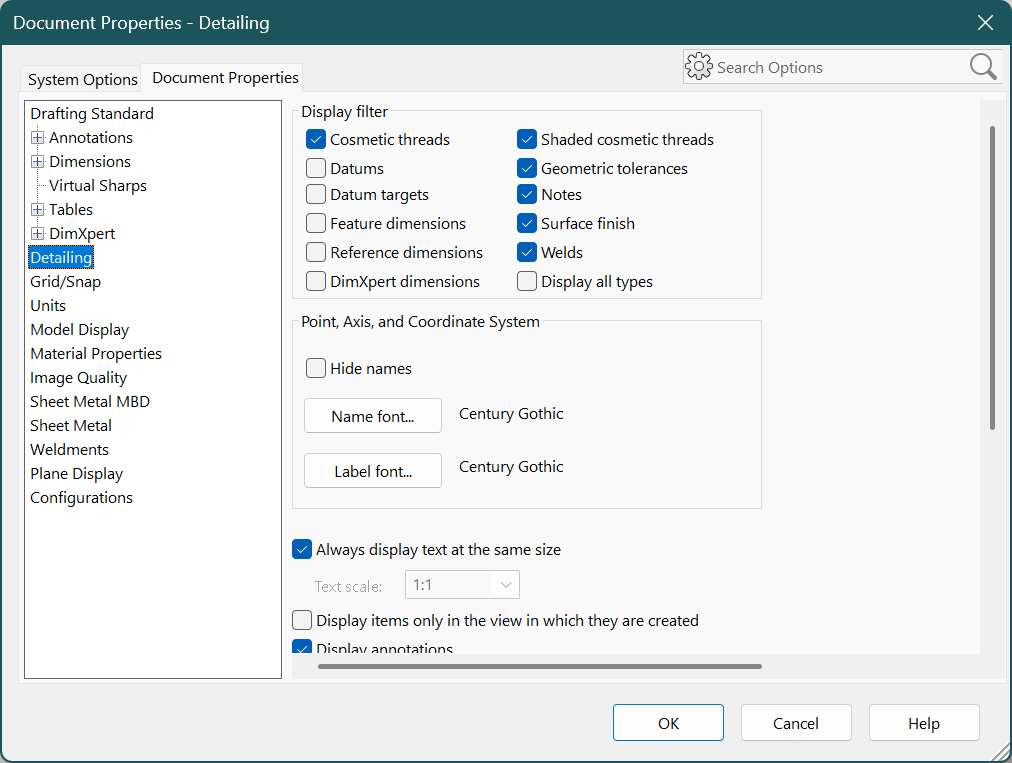
Almost every time, even after adding the cosmetic threads to your model, they may not appear on the screen.
This is typically a settings issue in Solidworks.
To solve this issue, in your part file, go to View > Hide/Show and select “All Annotations”.
Check Tools > Options > Document Properties > Detailing to make sure “Cosmetic threads” and “Display annotations” are both checked.
To make cosmetic threads visible in drawings, you must manually insert them into assembly views.
Navigate to the Annotations tab, select your view, and locate the cosmetic thread icon under “Annotations.”
Method 2: Built-in Thread Feature (Balanced Approach)
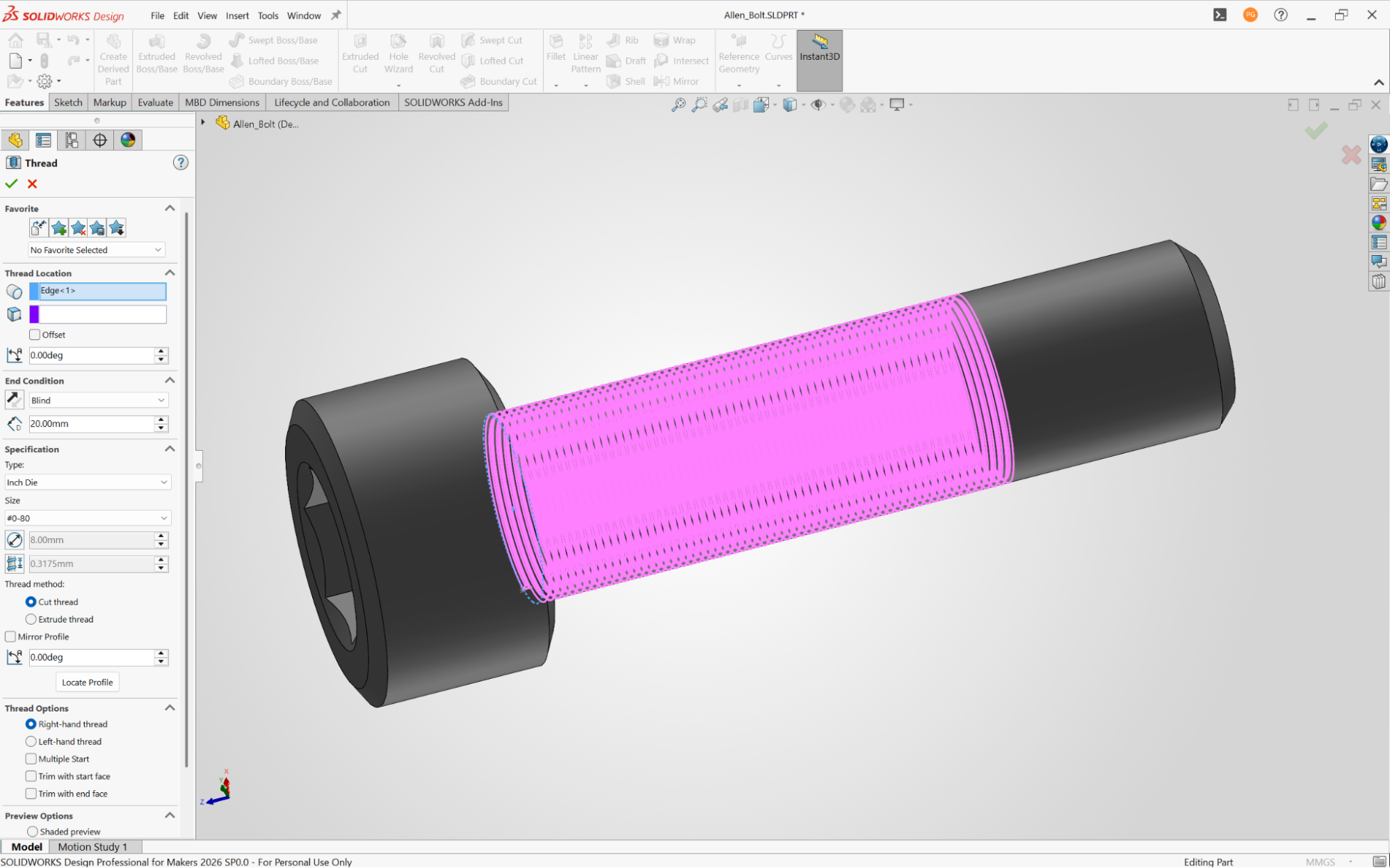
Cosmetic threads are good for show, but what do you do when you want an actual threaded feature on your models?
Since SolidWorks 2016, there has been a dedicated Thread feature that generates actual helical thread geometry using standard profiles.
Using this technique, you can eliminate the need for manual thread modeling, which can be challenging, time-consuming, and effort-intensive as well.
When to Use the Threading Feature in Solidworks
Again, rule → task → method, remember. This method is ideal when you need:
● Threads that are moderately accurate for visualization or basic fit checks.
● Standard thread types (UNC, UNF, metric, etc.)
● Threads that will appear in exports but do not have to be manufacturing-perfect.
● A starting point for customizing to specific tolerances.
The feature does not work well with tapered threads, multi-start threads, or custom thread forms.
For these, you’ll have to use the manual method.
1. Start with the base: Create a simple cylinder (for an external thread) or a hole (for an internal thread).
The diameter should match the nominal size of the thread you want (e.g., 0.250 inches for a 1/4-20 bolt).
2. Select the Start Edge: Choose the circular edge where you want the thread to begin.
3. Open the Feature: Go to Insert > Features > Thread.
4. Configure the Thread: The Thread dialog box requires four main settings:
Thread Location: Choose threaded hole (internal) or threaded shaft (external).
End Condition: Set how far or deep the thread extends.
Thread method: Use Cut Thread for internal threads (holes) and ExtrudeThread for external threads (shafts).
Specification: Select the correct thread standard and size from the lists.
5. Check the Preview: SolidWorks will show a preview.
If the thread looks wrong (backwards or inside out), check the “Mirror profile” option.
This happens often because of how the profile library is set up.
Confirm: Click OK.
SolidWorks will automatically create the thread geometry.
It will appear in the Feature Manager Tree and all subsequent views and exports.
Customising Thread Profiles
The Thread feature relies on profile library files located in your SolidWorks installation (typically at C:ProgramDataSOLIDWORKSSOLIDWORKS 20XXthread profiles).
You can open these files and change the dimensions if you need custom thread forms.
If you often create your own thread profiles, you should move the “thread profiles” folder to a different place.
Then, tell SolidWorks where this new folder is by going to Tools >Options > System Options > File Locations > Thread Profiles.
This way, if you update or reinstall SolidWorks, your custom profiles won’t be deleted.
Method 3: Manual Helix and Sweep (Full Control)
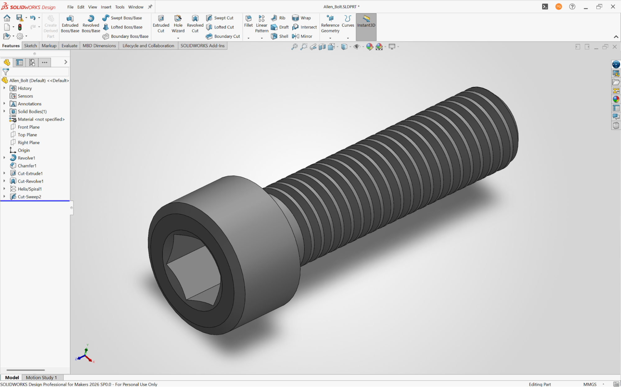
The manual method of using a helix curve and swept cut is best suited for 3D printing functional parts and custom thread forms.
You actually create and carve the profile of the thread onto the shaft with this technique.
When To Use Manual Thread Modeling
It’s better to use this technique only when you have sufficient experience with the SolidWorks software.
That said, you can use this method when you need:
● 3D printing parts with functional threads that must mate with actual hardware.
● Tapered pipe threads (such as NPT and BSPT)
● Multi-start threads or unique lead/pitch combinations
● Non-standard threads, such as wood screws or special fasteners.
● Thread modeling for CNC programming where exact geometry is important.
However, it takes time to configure the threads, which significantly slows down rebuild times.
Therefore, you should only use it when necessary.
Creating the Thread’s Path (The Helix)
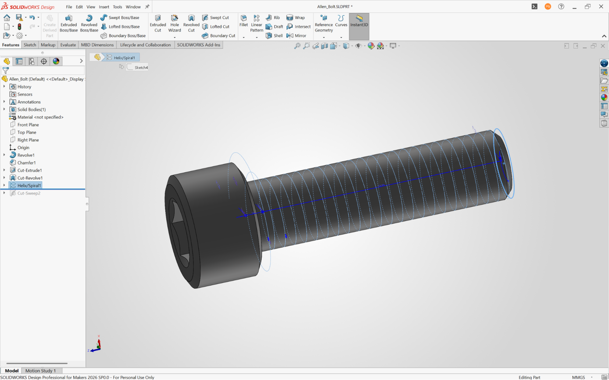
1. Start with your basic shape: This will be the cylinder (for an external screw thread) or the hole (for an internal thread).
We’ll assume you are making an external thread on a shaft.
2. Sketch the Circle: Start a new sketch on the end face of your cylinder.
To get the exact size, select the circular edge of the cylinder and use the Convert Entities tool.
This creates a perfect circle in your sketch that matches the shaft’s outer diameter.
3. Make the Helix: If you are already in the sketch command, then exit the sketch.
Go to Insert > Curve > Helix/Spiral.
In the Helix/Spiral options select:
Defined By: Choose “Height and Pitch.” This is standard for threads.
Pitch: Enter the distance between threads (e.g., 0.05 inches for a 1/4-20 thread, since 1/20 = 0.05).
For metric threads, refer to standard pitch values.
Height: Enter the length you want the thread to cover.
Direction: Select Clockwise (standard) or Counterclockwise.
Start angle: Keep this at zero unless you have a specific design reason to change it.
Finish: Click OK.
A spiral curve should now wrap around your cylinder.
Creating the Thread Profile Sketch
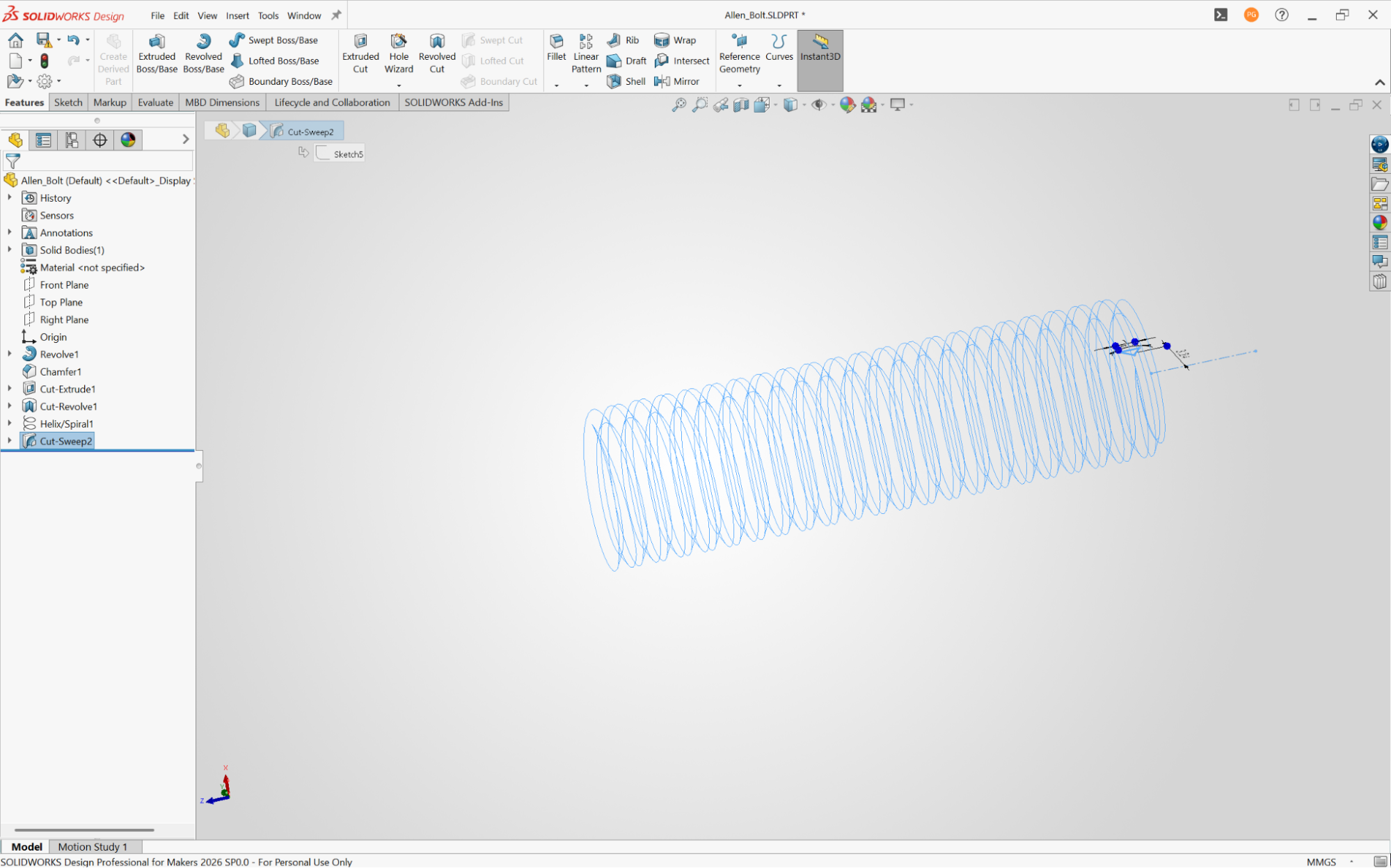
This is the most critical step: you must draw the exact shape of the thread’s cross-section.
1. Start a Sketch: Begin a new sketch on a plane that is perpendicular (at a right angle) to the start of your helix.
The top plane is usually the best choice if your helix starts at the zero-degree position.
2. Draw the Profile: Sketch a triangle for a standard triangular thread shape.
For a common 60-degree thread angle (like UNC/UNF), the triangle’s height should be about 0.6495 times the thread pitch.
The triangle’s base should extend slightly beyond the diameter of the main cylinder—about 0.003 inches of overlap works well.
3. Position the Sketch (The Key Step): You must lock this profile sketch to the helix path using a Pierce relation.
Select one point on your profile sketch (usually a corner of the triangle).
Hold the Ctrl key and select the helix curve. In the Properties panel, choose the Pierce relation.
This tells SOLIDWORKS exactly where the sweep operation should begin on the helix.
Symmetry (Optional Tip): It’s better to sketch only half of the profile, draw a center construction line, and then use the Mirror tool to create a perfectly symmetrical and consistent thread shape.
Sweep the Cut/Boss
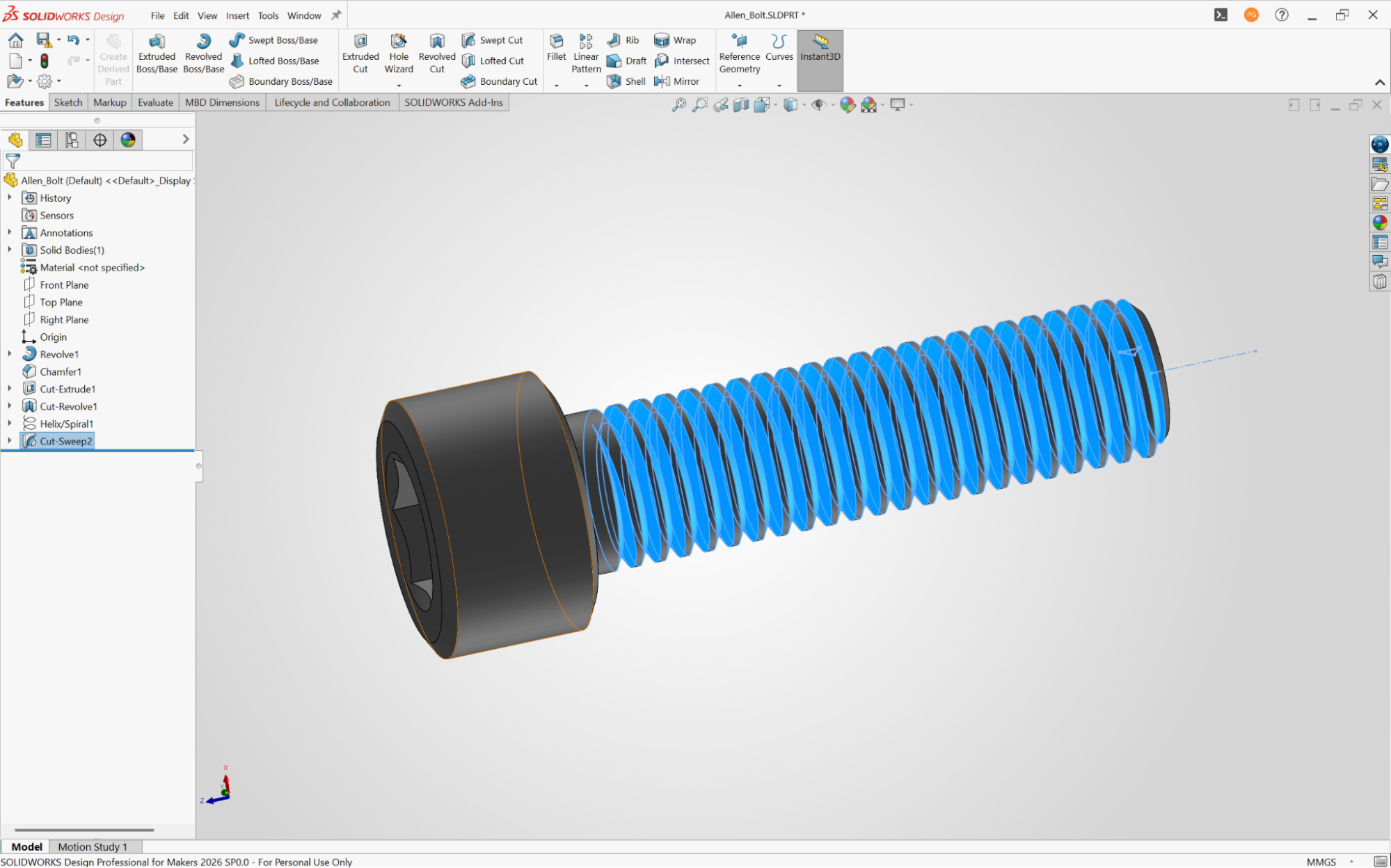
With your thread profile sketch and the helix path completed, initiate the Sweep feature:
● For internal threads (cutting material away), select Insert > Cut > Sweep.
● For external threads (adding material, or the more common ‘Cut’ method for modeling), select Insert > Boss/Base > Sweep (or Insert > Cut > Sweep).
In the Sweep PropertyManager:
● Profile: Click to select your thread profile sketch.
● Path: Click to select the Helix curve.
● Options: Generally, the default settings are fine.
If the result looks incorrect, you can try adjusting the “Profile Orientation” setting, such as selecting “Follow Path”.
Troubleshooting: It is possible that the preview shows the thread cutting in the incorrect direction, or that the profile is inverted.
In this case, you may need to mirror your original profile sketch or change the point on the sketch that is constrained by the Pierce relation to the path.
Finally, confirm the sweep to complete the fully modeled threads.
Add Lead-In and Cleanup
The last step in the whole process to give realism to your models is to add in a lead-in.
Real threads do not begin abruptly but rather with a lead-in or chamfer.
You can do this with a simple revolve cut and a triangular sketch, or add a chamfer to the edge if you have a clean edge to work with.
You should also consider adding a relief groove or letting the thread end run naturally based on your modeling needs.
Common Problems and How to Solve Them
Here are some of the problems that usually show up and the solutions.
Sweep Preview does not appear:
Your sketch profile is probably not properly connected to the helix.
Check for a “Pierce” relationship between a point in your sketch and the helix curve.
Also, make sure your sketch is perpendicular to the helix start point.
The thread looks inside-out or backwards:
To fix this, mirror your profile sketch, or if you’re using the Thread feature, select the “Mirror profile” option from the dialogue box.
This occurs when the profile orientation does not correspond to the cylinder geometry.
The thread self-intersects after the first revolution:
Your profile is too big.
The thread depth (the height of your triangle) should be significantly smaller than the pitch.
Standard thread depth ranges from 0.6 to 0.65 times the pitch of the thread.
Reduce the thread profile’s size and try again.
Extensive Rebuilding Times:
If you’re using manual helix-and-sweep threads and your file is crawling, make a simplified configuration.
Suppress the thread features in your main assembly configuration and only enable them in the “detailed” or “for export” settings.
Most assemblies are not required to display thread geometry.
Cosmetic threads are not visible in my drawing:
Check two things: First, ensure that the cosmetic thread annotation is not hidden (right-click the “Annotations” folder in the feature tree and select “Visibility”).
To add model items to your drawing, go to the Annotations tab and select cosmetic threads.
So, which method should you use?
While you can choose to use any of the above three, after all, they are all valid methods.
But I believe, after reading through the pros and cons of each method, you kind of get an idea about which one you should be using.
Here’s what my general approach is towards using threads in SolidWorks:
Cosmetic threads are suitable for use in everyday design work where threads will be added during manufacturing.
They’re quick, they appear on drawings, and they don’t slow down your assemblies.
The thread feature is suitable for visualization, customer presentations, and moderately detailed models.
It provides actual geometry without the hassle of manual modeling and is accurate enough for most applications.
Manual helix and sweep are ideal for 3D printing functional parts, CNC programming, or creating custom thread forms.
Having extra control is necessary to ensure your threads function properly in the real world, despite the additional effort.
Summary
Threads in SolidWorks don’t need to be necessarily complicated.
Although, they tend to be so sometimes.
For the majority of your 3D modeling work, simply start with the cosmetic threads.
Then once you build confidence, use the Thread Feature for actual geometry.
And finally, the helix-and-sweep method when you need complete control over your threads.
The key for you is to understand the tradeoffs between the speed, detail, and file performance of each model.
A cosmetic thread takes seconds to create and has no effect on rebuild time.
A manually modeled thread can take minutes to set up, slowing down your entire assembly.
Feel free to leave comments and contact us if you have any questions about creating threads or anything else SolidWorks-related.