How to Import Google Earth Data into Civil 3D
When working with site planning, land development, or roadway design, the use of accurate, easily accessible, and up-to-date topographical data, such as…
When working with site planning, land development, or roadway design, the use of accurate, easily accessible, and up-to-date topographical data, such as satellite imagery or Digital Elevation Modelling (DEM) map data, becomes a must.
This is where the integration of Google Earth Pro with Civil 3D comes in handy to ensure precision in both the analysis, design and quantification.
To learn how to do this efficiently without missing any crucial step, make sure to read through this well-detailed article to enhance and boost your design work.
Here is a video version of this article.
Inputting New Settings for the Civil 3D Drawing
Assuming you are starting with a completely new Civil 3D drawing, you need to ensure that your drawing settings are set.
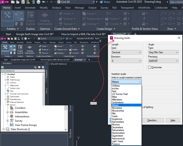
In this case, I will open a new drawing using the Metric Civil 3D drawing template, and then I will confirm my units by using the keyboard shortcut UN.
The Drawing Units window will pop up, and I will input my preferred units here.
In this case, under the Insertion Scale, I will use Meters and the rest as depicted in the image below.
Identifying and Marking Your Project’s Location Using Google Earth
Once your drawing is set up, it is now time to launch your Google Earth Pro software, enter your project’s geographical area name or coordinates in the search bar and zoom in for a more detailed view of the area.
In this tutorial, our project’s geographical location will be Nakuru, Kenya.
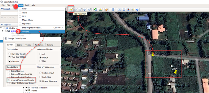
Use the Placemark tool to mark at least two points in the project area boundary, which should act as your anchor once you bring the image into Civil 3D.
As shown in the exhibit below, navigate to Tools, select Options, and under the Show lat/long section, change the placemark properties from longitude/latitude to Eastings and Northings by selecting the Universal Transverse Mercator (UTM) system.
Make sure to copy the details of the latitudes and longitudes of the two place markers in a Notepad as shown below, as the same data will be required later on in the orientation of the image in Civil 3D.
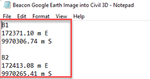
Note: Civil 3D recognizes only Eastings and Northings coordinates.
Once that is done, it is time to export your Earth satellite image, and to achieve this, navigate to View, reset the tilt and compass for a plan view, and then save the image.
Navigate to File, click on SAVE and then click on Save Place as or Save Image.
Modify the resolution or scale as needed and save the image in JPEG or PNG format to ensure precision when importing data into Civil 3D.
Importing Project’s Imagery from Google Earth to Civil 3D
If you want to bring the Earth satellite imagery saved from Google Earth Pro into Civil 3D, you will first need to input two circles into your Civil 3D drawing, which will act as anchors for the placeholders from Google Earth Pro.
After that, the two random circles that you drew will need to be positioned correctly in the Civil 3D drawing, using the exact coordinates that were with the place makers.
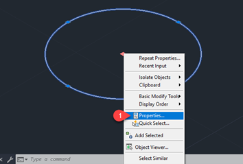
To change the coordinates of the circles, navigate to the Geometry option, select Properties and paste the respective Eastings (center X) and Northings (center Y) to the two circles as shown in the exhibit below.
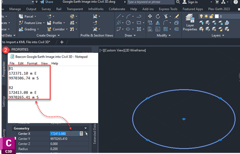
After ensuring that your place makers are using the coordinates copied from the Google Earth Pro place makers, next, navigate to the Insert tab, and under Reference, use the Attach or use Xref tool to place the Google Earth imagery that you had saved.
In this case, use the Relative Path Type to attach the image to Civil 3D.
The next critical step would be to align the Google Earth imagery with the two placemarks (circles) on Civil 3D by using the Align tool in the Modify panel.
The Aligning tool allows you to scale up or down the imagery as required, and it ensures that the two placemarks align with the circles in Civil 3D perfectly.
So, how do you align an image in Civil 3D?
To do this, select the first point destination from the attached imagery (in this case, the pinpoint at which the place maker has its pin-propped as shown in the exhibit below), then click at the centre of the first circle.
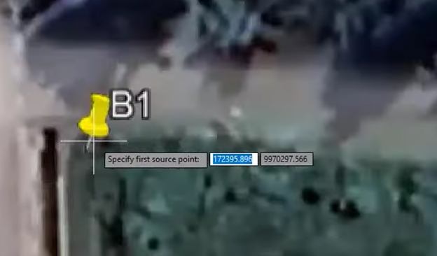
Then do the same for the second circle and the second point destination from the imagery.
Feel free to check whether the two placemarks on the imagery align with the two circles by toggling the Show Image option under the Image tab.

Importing Google Earth Points, Eastings, and Northings to Civil 3D
To import all the rich data extracted from Google Earth Pro in terms of Points that have Coordinates, start by creating a new drawing and ensure that your drawing settings are correct and explained above.
Then launch your Google Earth Pro software and in the search bar, input your project’s geographical location.
Set the view to plan using the Tilt and Compass feature to get the plan view, as shown in the exhibit below.
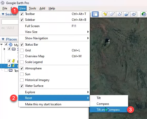
After that, from the quick access toolbar, click on the Add Path option, and a Google Earth – New Path window will open from where you will give the name, description, etc. of your path and adjust the settings as preferred.

For the best Digital Elevation Modelling (DEM) data, set the Altitude settings as Clamped to ground and the Measurements settings in kilometers as shown in the exhibit below.
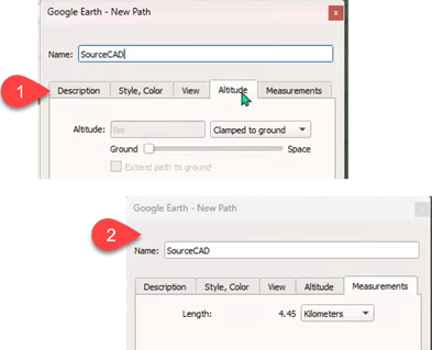
Trace out your path continuously on your project geographical location by holding down your left mouse button and clicking OK in the Google Earth – New Path pop-up window.
You can now save the path as a KMZ or KML file by clicking on it in the Places window in Google Earth Pro, as shown below.
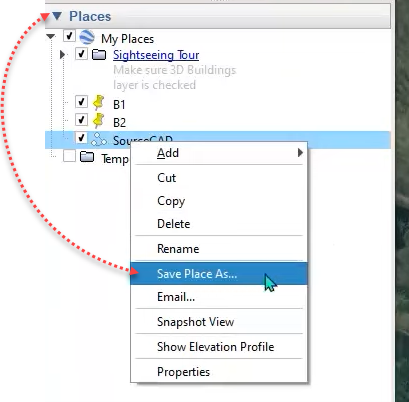
Using the GPS Visualizer website, convert the file to plain text with UTM coordinates by uploading the file, taking it through the prompts and then downloading it as a text file.
Once the text file is downloaded, open it in your Excel, edit the data to retain only Points, Eastings, Northings, Elevations and Descriptions and save it as a CSV file.
To best understand this procedure, make sure to check out the above embedded YouTube video on How to Import Google Earth data into Civil 3D.
Now, to import the points into your drawing, select Points in the Civil 3D’s Point Creation tool, then specify the point file format: PENZD (comma delimited)—Points, Eastings, Northings, Elevation, and Description in the Import Points dialogue as shown in the exhibit below:
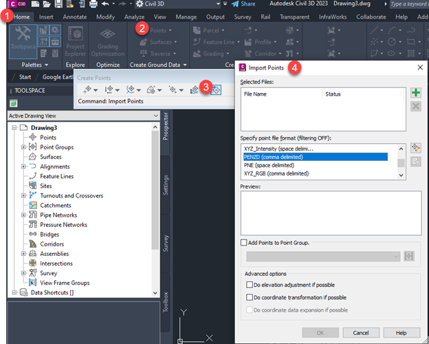
For best practices with Civil 3D data, add your points to a Point Group and name the file as preferred and click on OK to finalize the importation of your DEM points into Civil 3D.
Double-click your mouse centre wheel button to zoom extents and view all your points on your drawing interface.
Creating the TIN Surface in Civil 3D
In civil 3D, DEM is essential when it comes to technical projects that revolve around cut-and-fill, volume analysis, drainage design, road grading, etc.
Now that you have your DEM points in your workspace, you can proceed with the modelling of the TIN surface.
First, navigate to the Surface tool in Civil 3D, create a shell for your TIN surface, then under the surface definition, add the Point Group to create a 3D surface from the imported points as shown in the exhibit below.
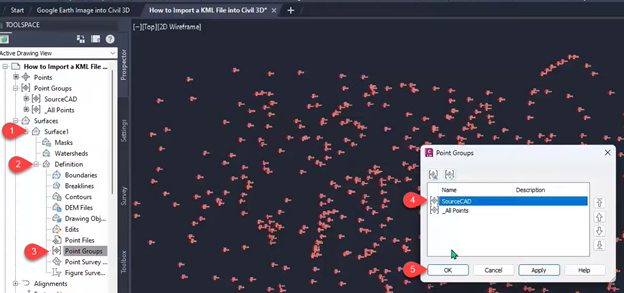
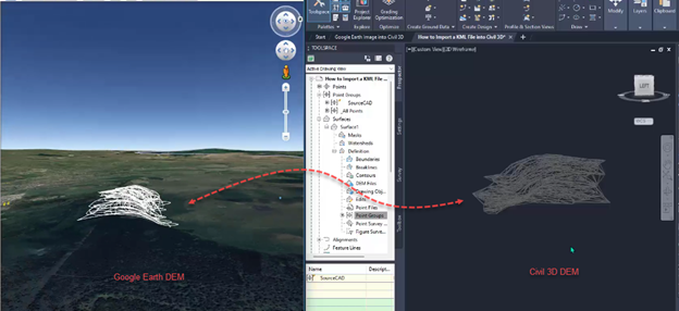
This TIN surface represents the existing ground, capturing the natural elevations and slopes of your project site.
Using Chatgpt to Import Google Earth Data Points into Civil 3D
Did you know that you can use ChatGPT to provide you with the DEM points?
To get your points, Eastings, Northings, Elevation and Description for your project, you can start by creating custom prompts as shown in the image below.
Sample of the ChatGPT prompt:
“Could you kindly provide me with about 20 points that I can use to create a topographical map in Civil 3D
My project is using the UTM coordinate system and is located in Kenya, Nairobi County, south of the equator.
Tabulate the points with the following headlines: Points, Eastings, Northings, Elevation, and Description.
The project is in Metric, make the point have about three decimal places.”
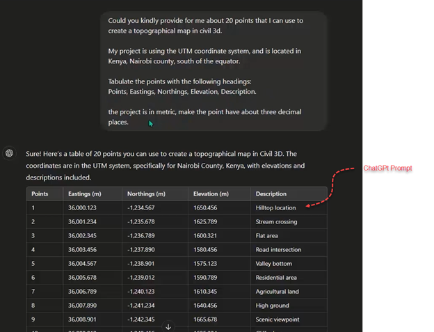
Copy and paste the ChatGPT output into your Excel software, then save it as a CSV.
File as explained above and then import the CSV file into your Civil 3D project, and create your 3D Digital Elevation Model, repeating the above guided steps.
Note: ChatGPT will not give you workable data sometimes, but you can use it for experimentation.
Frequently Asked Questions
These are some of the common questions our students ask quite frequently.
Do I need to have any plugins to import KML/KMZ files?
No.
Civil 3D has an already built-in Import KML and KMZ function to enable one to import Google Earth points, but this option is limited when working with point DEM data from Google Earth.
Civil 3D will only import the KML or KMZ files as line work rather than feature lines that have elevation data or points that can be used for designing topographical or DEM maps.
What is the difference between KMZ and KML files?
KML is a file format that stores geographical data in XML format, whereas KMZ is a compressed file format containing one or more KML files and their associated resources.
But when it comes to Google Earth Pro and Civil 3D, feel free to use either of them interchangeably, and both are recognizable by the software.
Can I adjust the imagery’s resolution after importing it into Civil 3D?
Imagery resolution captured from Google Earth depends on the source and nature of the project.
When exporting your image from Google Earth Pro, make sure to use the preferred image resolution for your project, as shown in the exhibit below:
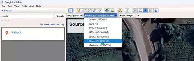
Once the Google Earth Pro satellite imagery is brought into Civil 3D, ensure to adjust the image scale to fit within your project’s dimensions.
Summary
After reading the above article, you are now fully equipped when it comes to working with Google Earth Pro and Civil 3D when it comes to making satellite maps or topographical maps using DEM data from Google Earth.
Make sure to watch the YouTube video to appreciate how easy the process can be and how this can help you save on time when it comes to your everyday design work as an engineer, architect, construction professional, student or design enthusiast.
Feel free to let me know which option works best for you or which other topics you would like to learn next.