A detailed guide to 3D printing infills and which one should you use
Infill is the answer to the age-old question in 3D printing: weight vs. strength. It is one of the most underrated tools in additive manufacturing, which is…
Infill is the answer to the age-old question in 3D printing: weight vs. strength.
It is one of the most underrated tools in additive manufacturing, which is quite unique and a time and money saver when you compare it with traditional subtractive manufacturing.
Getting your infill right is more than just saving a few grams of material.
The correct infill pattern and density can help you optimize the model for strength vs. aesthetics.
You can cut the print time by almost half using a lightning infill pattern.
Similarly, you can increase the strength of the model by keeping its weight low using the gyroid pattern.
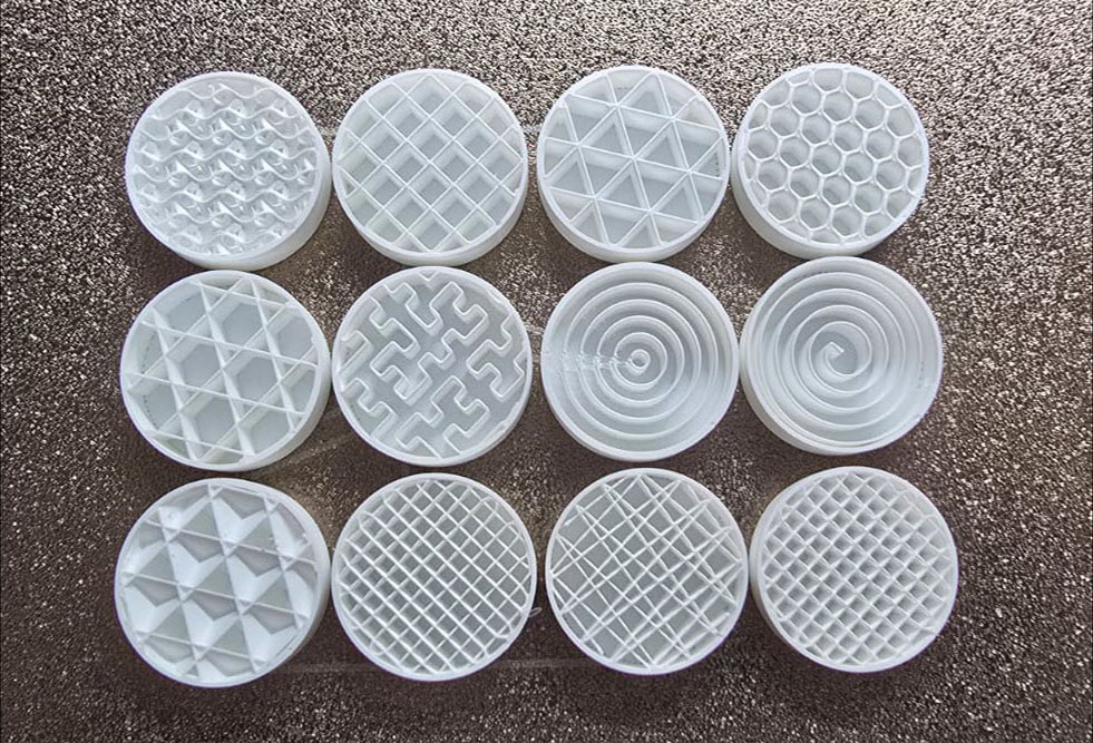
In many ways, the choice of infill pattern works hand-in-hand with your 3D printing material selection to determine final part strength.
However, the trick is to just get it right.
And as straightforward as it might seem, it often isn’t.
In this article, we’ll explore the world of 3D printing infill, understand the various types, and give you recommendations on which infill YOU should use, based on our experiences.
Filling the Gaps: What is Infill?
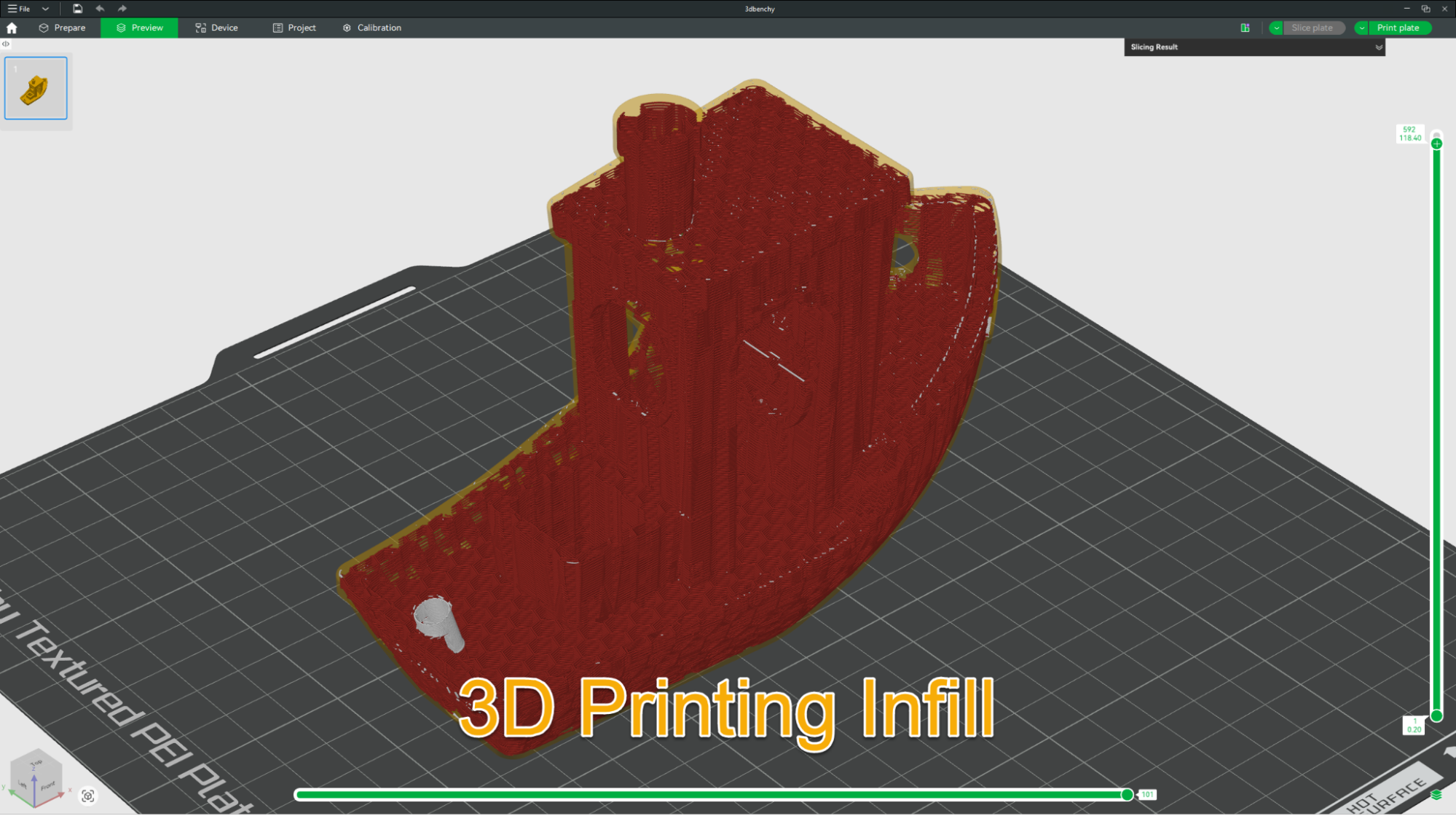
In the context of additive manufacturing (AM), infill refers to the internal lattice structure that forms the inside of a 3D-printed part.
The term “infill” is rooted in the early days of industrial casting, where “fill” materials were used to occupy space without adding significant weight to the cast.
In 3D printing, we have moved away from the “solid or hollow” binary of traditional manufacturing.
Instead, we use complex geometries to create parts that are functionally robust while remaining lightweight.
Infill is what supports your top layers and providesthe structurall integrity needed for functional parts.
Without it, your top surfaces would have nothing to rest on and would simply sag into the abyss of your model.
Why Does Infill Matter?
Why not just print everything 100% solid? While a solid part is super strong, it’s often overkill, especially when you’re using 3D printing.
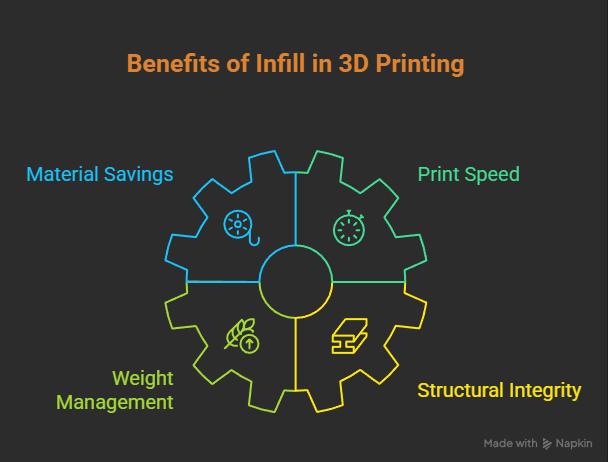
Here is why choosing the right infill can uplift your projects:
Material Savings: Using a 15% infill instead of 100% can save you a massive amount of filament.
Print Speed: Less plastic to extrude means your printer finishes faster.
Weight Management: Essential for drones or moving mechanical parts where every gram counts.
Structural Integrity: Different patterns handle stress (tension vs. compression) in unique ways.
Which Infill Pattern to Use in 3D Prints?
Choosing the right infill pattern can literally make or break your 3D parts. It’s more than just an aesthetic choice; it’s also a decision about how stresses will travel through your part.
From a mechanical engineering perspective, different patterns handle anisotropy (strength differing based on direction) in various ways.
The Standard Weight Bearers: 2D Patterns
2D patterns are “stacked” identically, layer by layer.
They are fast and provide excellent vertical support.
Grid
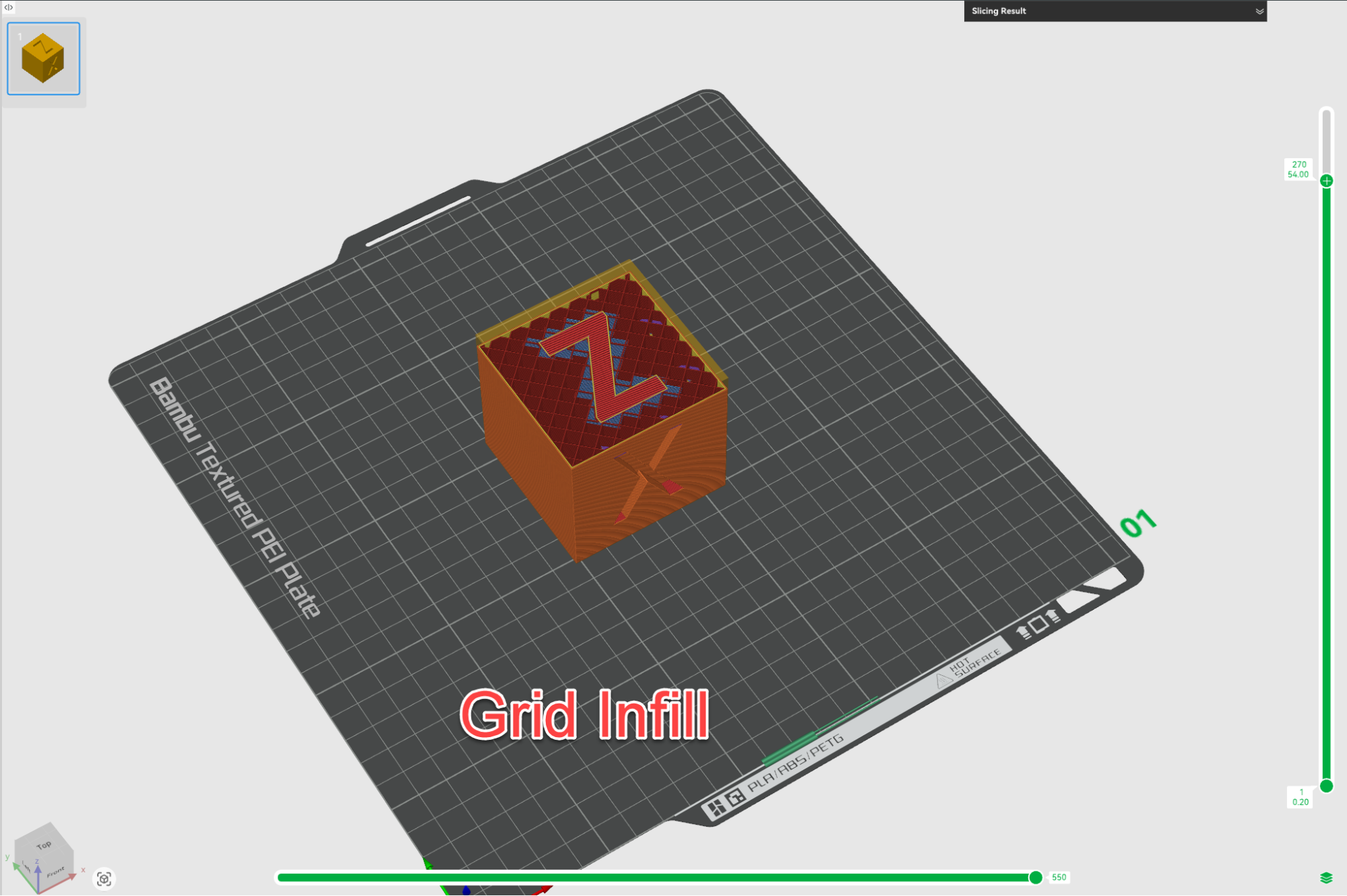
This is the most common pattern. It creates a series of squares.
While it is super strong in the Z-axis, it has a major flaw: the lines cross over each other on the same layer.
On high-speed machines like the Bambu Lab A1, this defect can cause the nozzle to “clip” the previous lines.
Lines
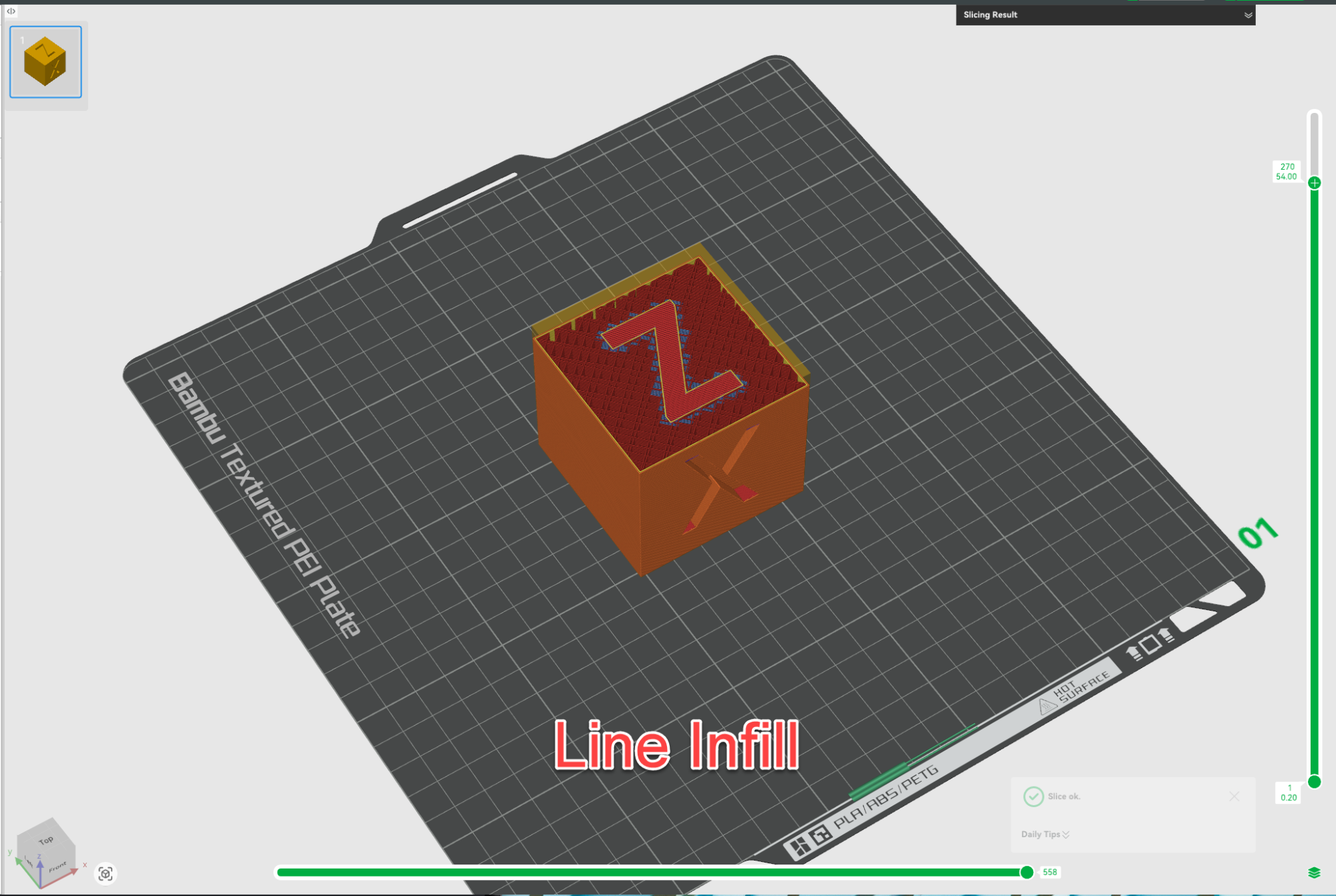
Similar to Grid, but layers alternate directions.
It is slightly weaker than Grid but much faster and uses less material.
Tri-Hexagonal
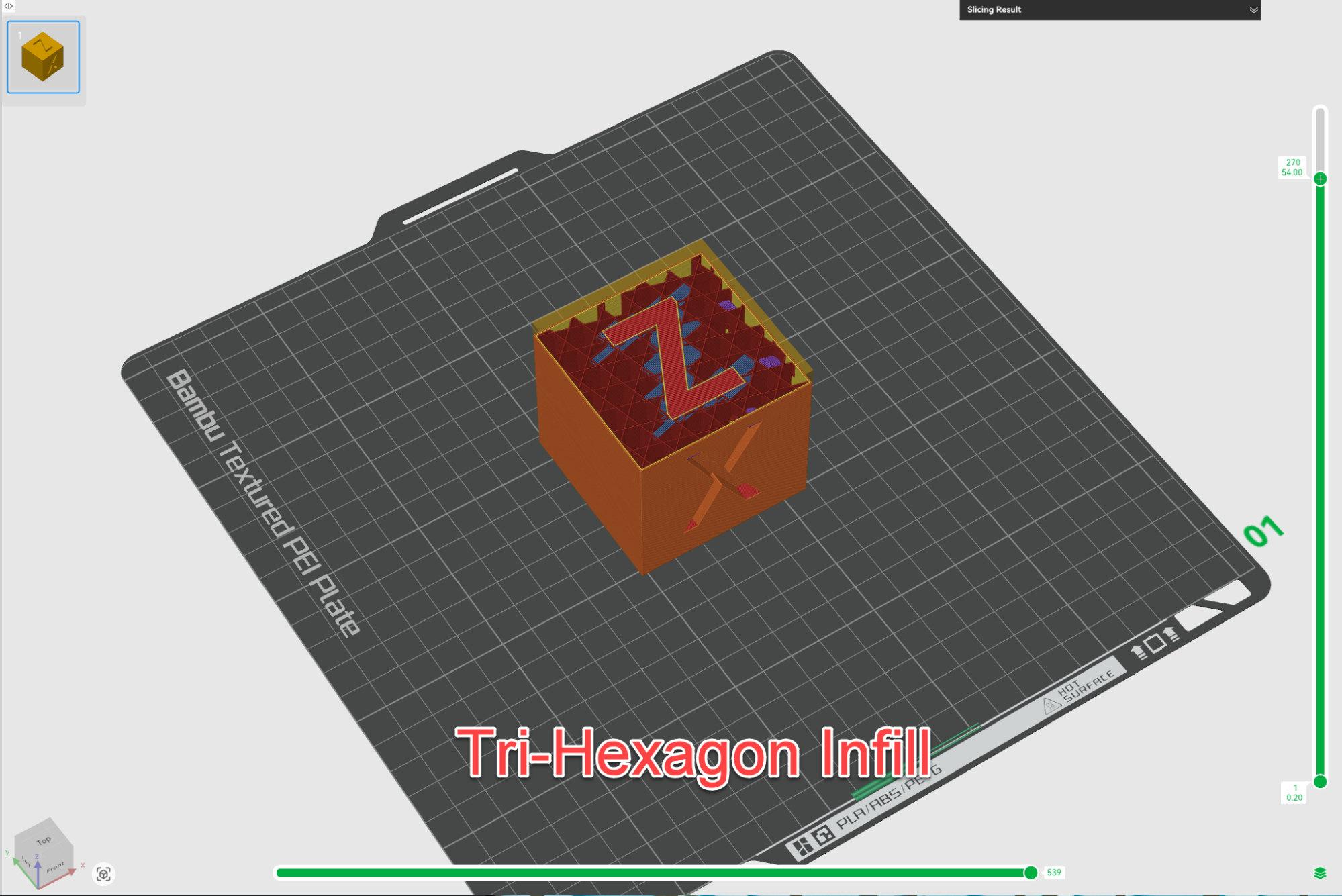
An amazing choice for structural integrity.
By combining triangles and hexagons, it creates a rigid lattice that resists shifting in the X and Y planes.
The Modern Additions: 3D and Specialized Patterns
These patterns change as they move up the Z-axis, offering more uniform strength in all directions or specialized mechanical properties.
Gyroid
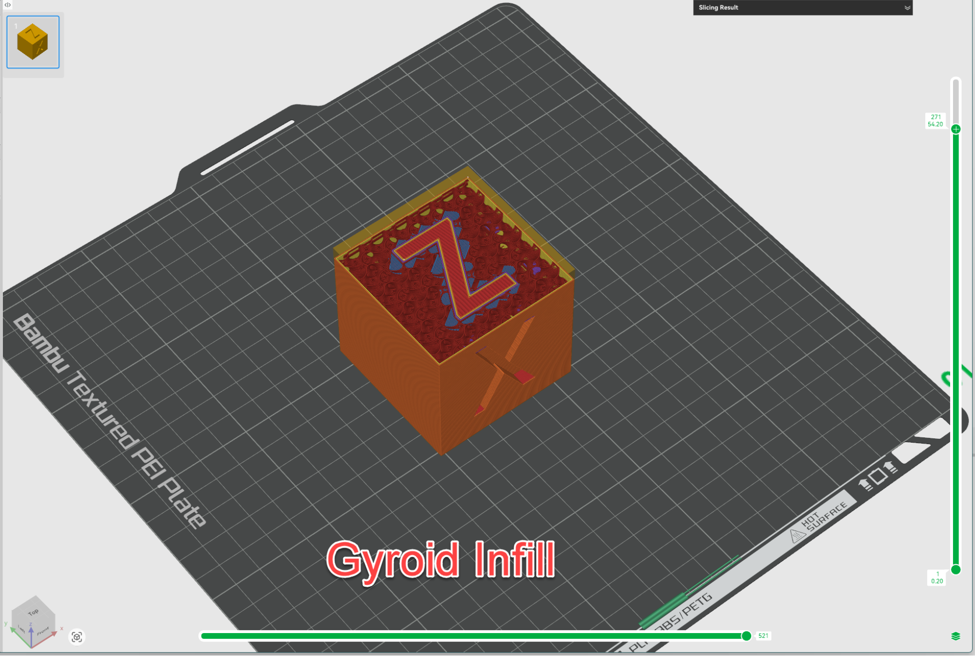
This is arguably the most mesmerizing and functional pattern available.
It is a “triply periodic minimal surface. ” Because it doesn’t have crossing lines, it eliminates nozzle clicking.
More importantly, it is isotropic, meaning your part won’t have a specific “weak point” when twisted or bent.
This is a perfect example of how printer hardware capabilities influence design decisions and is a core principle of Design for Manufacturing.
Cubic
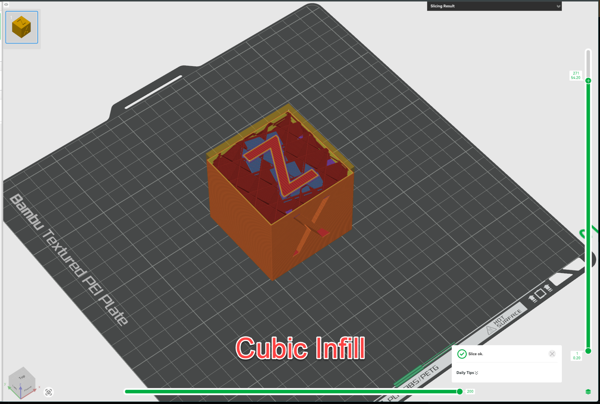
This pattern creates a series of tilted cubes.
It provides excellent support for top layers and is very stiff.
If you are printing a tool handle, Cubic is a fantastic choice to ensure it feels solid.
Concentric
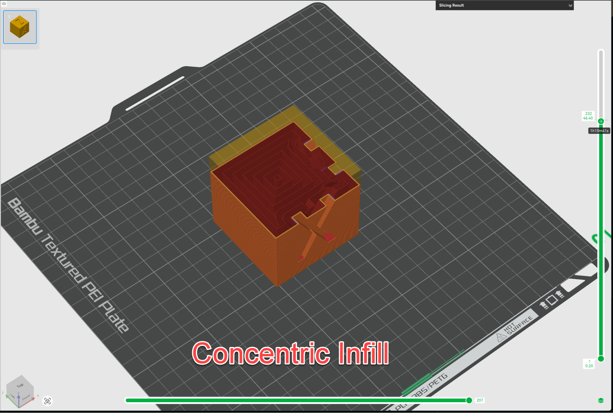
This pattern mimics the outer shape of your walls, moving inward.
It is the go-to for parts printed with transparent filament because the internal structure looks uniform from the outside.
It’s also handy for parts that need to be flexible, as it allows for even compression.
Cross and Cross 3D
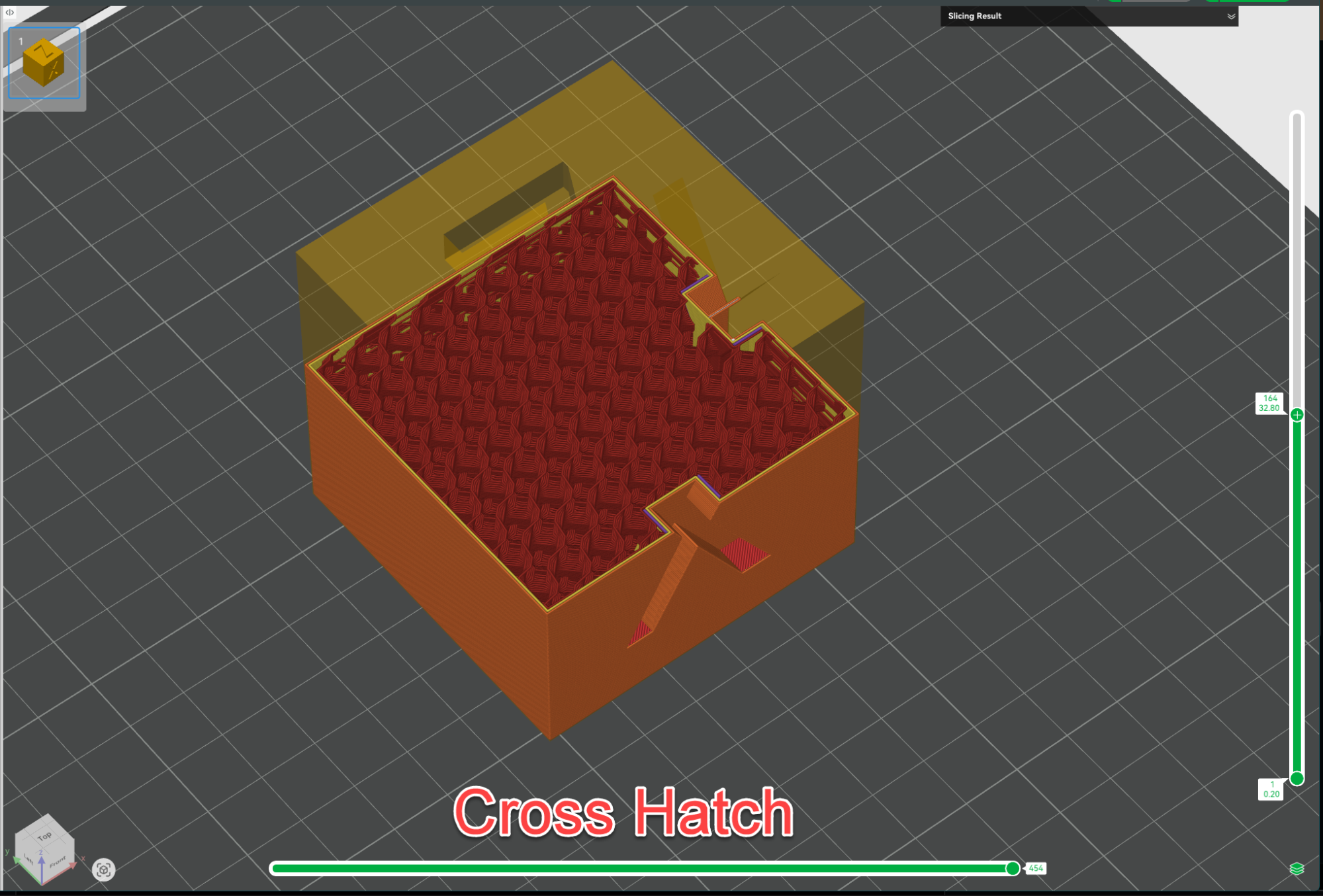
These are specifically designed for flexible materials like TPU.
They avoid crossing lines and sharp corners, which reduces the chance of the nozzle “clogging” or “blobbing” when printing soft, elastic filaments.
Fast Infills: Speed-Focused Patterns
When strength isn’t the priority, but time and filament savings are, these patterns are incredibly handy.
Lightning
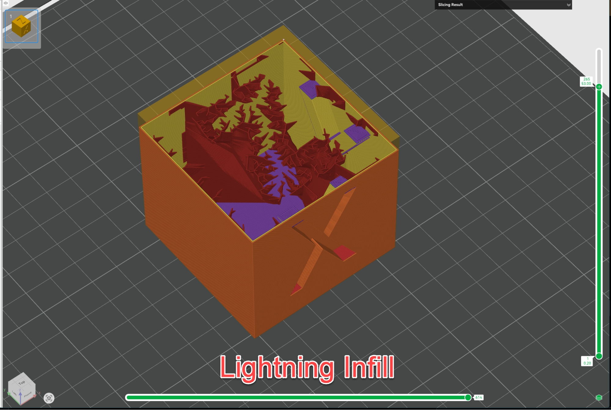
This is a relatively new and amazing addition to 3D printing slicer software.
It generates a structure that looks like a lightning bolt or a tree root, branching out to support only the internal ceilings of your model.
It leaves the base almost hollow, making it the king of material efficiency for decorative busts or statues.
Zig-Zag
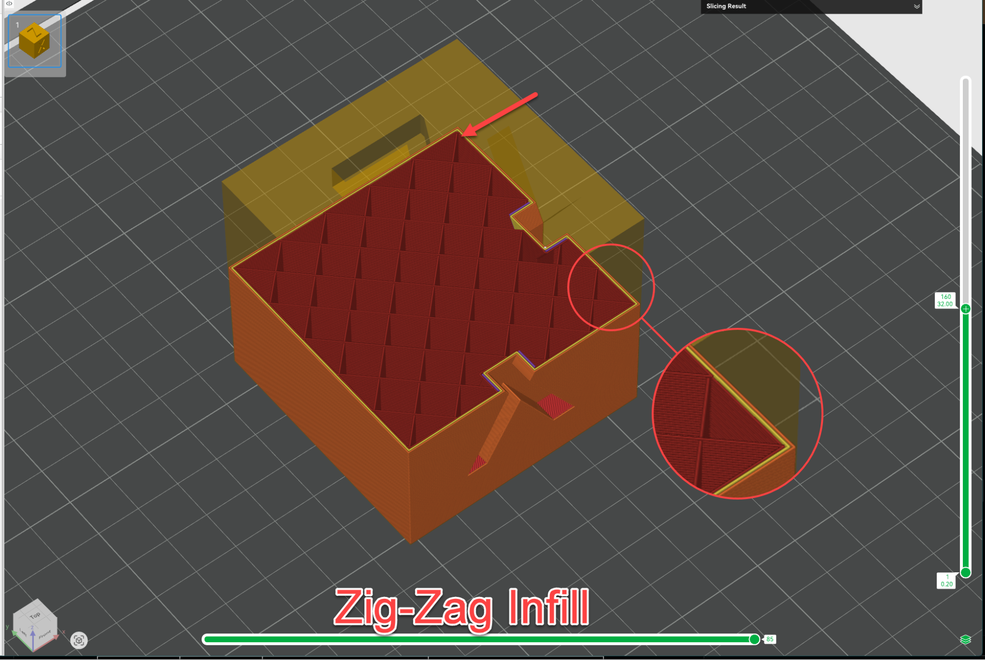
Similar to lines, but the printer doesn’t stop extruding at the end of a line; it “zig-zags” back.
This is excellent for adhesion and very fast for quick prototypes.
Density Decisions: A Heavy Choice
One of the biggest misconceptions many 3D printing users have is that higher infill density always equals a better part.
In reality, the relationship between density and strength follows a curve of diminishing returns.
Density Range | Category | Best Use Case | SourceCAD’s Take |
0% – 15% | Low | Figurines, display models, “visual-only” prototypes. | Great for “shelf queens” that just need to look pretty. |
15% – 50% | Standard | The “Sweet Spot”: brackets, household fixes, and standard parts. | 20% Gyroid is usually all you need for 90% of prints. |
50% – 90% | High | Heavy-duty gears, functional tools, and load-bearing mounts. | Use sparingly. Often, adding walls is better than going above 60%. |
100% | Solid | Lithophanes, transparent parts, or threaded rods. | Essential for lithophanes to block light correctly! |
You can learn more about designing parts with proper tolerances and fit in our DFM for 3D Printing course.
Pro Tip: Some slicers allow for Variable Infill Density.
This means you can have 10% density at the bottom of a print and 50% at the top near a mounting hole.
In Bambu Studio, you can use “Modifiers” to achieve this, placing strength exactly where you need it without wasting material elsewhere.
Essential Infill Settings: Optimizing Patterns
Knowing the patterns is step one. Mastering the settings is step two. Here are the “hidden gems” in your slicer settings (found in Cura, PrusaSlicer, and Bambu Studio).
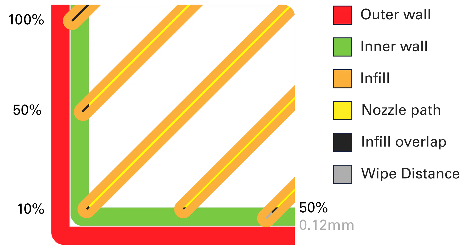
Infill/Wall Overlap
Ultimaker Curahttps://support.ultimaker.com/s/article/1667411002588
If you see small gaps between your outer shell and the internal infill, your part is structurally compromised.
This setting determines how much the infill “bites” into the wall.
Default: Usually 15%.
Recommendation: Bump it up to 25-30% for functional parts. This “welds” the interior to the exterior for maximum strength.
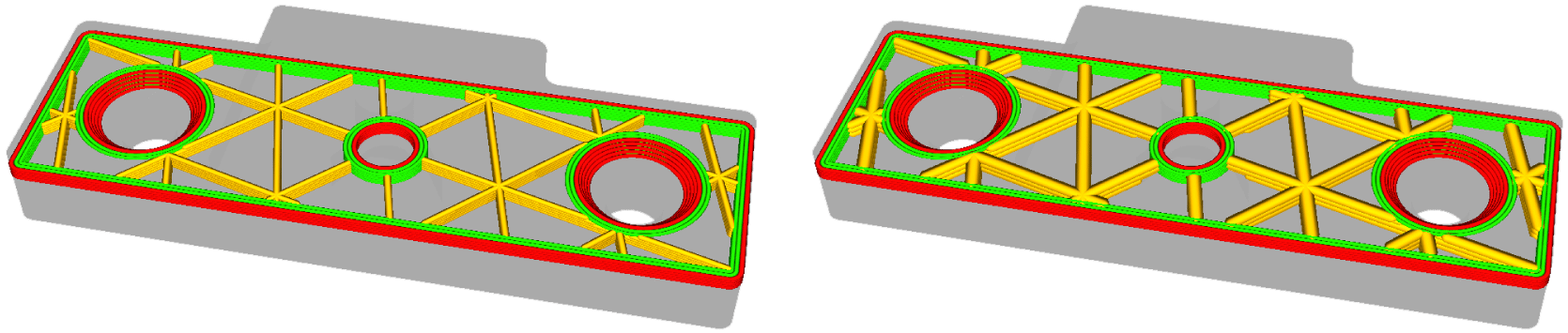
Infill Combination (Layer Thickness)
Ultimaker Curahttps://support.ultimaker.com/s/article/1667411002588&sa=D&source=docs&ust=1768638092881967&usg=AOvVaw16cCQuy5I30tsVf-HE1GcN
Infill can be printed thicker than your walls.
If you’re printing detailed walls at 0.1 mm layer height, you can set your infill to print every other layer at 0.2 mm.
This drastically reduces the print time because the nozzle has to do half as many passes for the interior.
Infill Angle
By default, most infill prints at 45 degrees.
However, if you have a part with specific weak points, you can rotate the Infill Angle to ensure the lines run perpendicular to the stress force, reinforcing the part exactly where it needs it.
Troubleshooting: When Infill Goes Wrong
Even though there’s little that can go wrong while printing infill, mishaps can occur. Here is how to fix common infill issues:
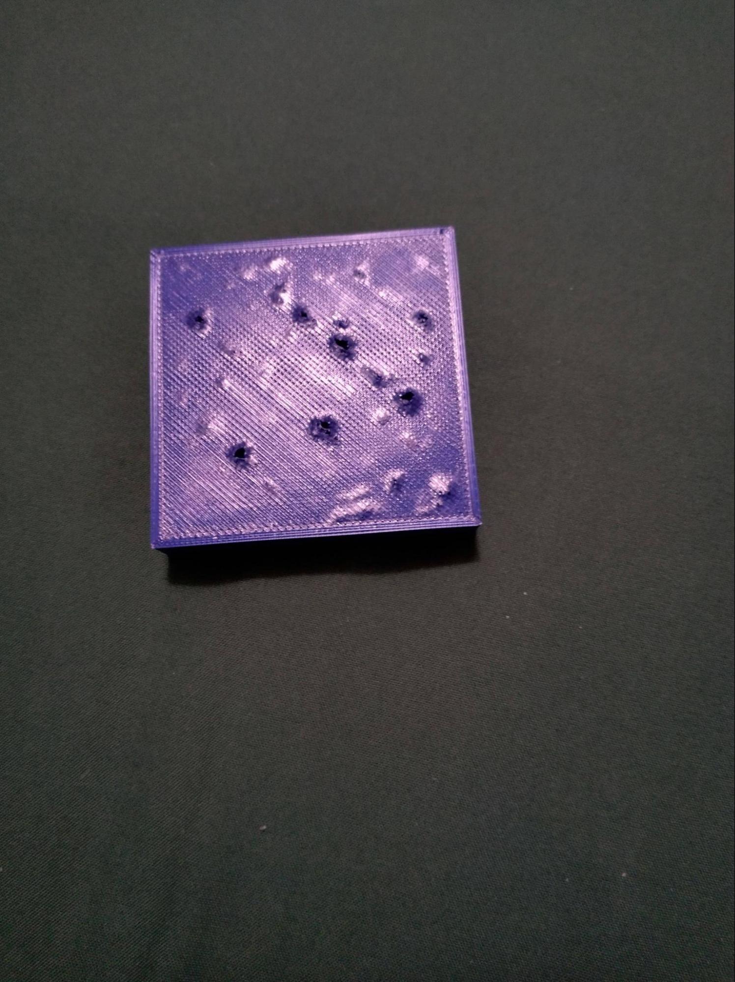
Pillowing:
Orthodox-Waffle via Reddithttps://www.reddit.com/r/3Dprinting/comments/smf3rf/tpu_what_is_causing_this_pitting_only_occurs_on/
If your top surface looks bumpy or has holes in it, your infill isn’t supporting the roof.
Fix: Don’t just increase infill density! Instead, increase your top shell layers (aim for at least 4–5 layers) or switch to a more supportive pattern, like Gyroid.
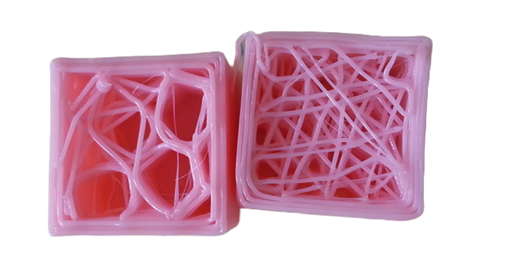
Weak/Stringy Infill
rcleacock via Reprap forum https://reprap.org/forum/read.php?1,403012
If the inside looks like a spiderweb, the 3D printer is likely under-extruding.
Fix: Infill is often printed faster than walls. Slow down the infill speed in your slicer or bump up the nozzle temperature by 5°C to ensure the plastic flows smoothly enough.
Ghosting
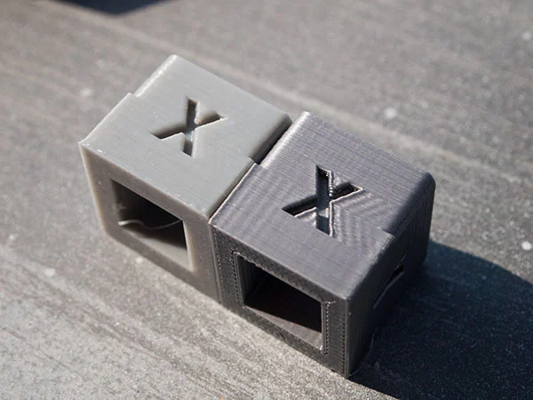
orcinus via Thingiversehttps://www.thingiverse.com/thing:277394
Can you see the pattern showing through the outer walls
Fix: Your wall thickness is too thin. Ensure you have at least 2-3 walls (perimeters) so the infill doesn’t push against the visible surface.
Related Resources
Want to dive deeper into 3D printing? Check out these resources:
3D Printing Material Properties Cheat Sheet [PDF] – Master material selection for optimal results
DFM for 3D Printing Course – Design parts that print successfully the first time
Fusion 360 Tips and Tricks – Optimize your CAD workflow for 3D printing
All 3D Printing Articles – Explore our complete 3D printing blog library
Summary: The Final Layer
Infill is unique to 3D printing and is the secret sauce that can transform your heavy block of plastic into a lightweight engineered marvel.
You don’t need to just depend on the default settings; in fact, you should deter away from them, often!
Actually choosing your own infill density and pattern, you can truly tune your CAD model to suit the rigors of the real-world requirements.
Furthermore, like almost every other 3D printing setting, infill isn’t universal, and each parameter varies based on the model.
Whether you are chasing the amazing aesthetic of a Gyroid vase, the sheer strength of a Cubic bracket, or the efficiency of Lightning for a quick prototype, remember that every print is a data point.
You learn from each 3D print, iterate through it, and use better settings the next time.
Experiment with those “expert” slicer settings, push your walls to the limit, and find the geometry that works for your specific project.
If you have any questions, doubts, or need help with setting up your 3D printing parts, feel free to leave a comment below.