3D Printing using AutoCAD The Complete guide
AutoCAD has been in use since 1982, but it is not the first software that comes to mind when you think about 3D printing. Most people know AutoCAD for its…
AutoCAD has been in use since 1982, but it is not the first software that comes to mind when you think about 3D printing.
Most people know AutoCAD for its use in drafting and technical drawings; however, it is quite useful even for 3D printing.
And it makes complete sense if you are already used to AutoCAD, its commands, its interface, and the general workflow.
You don’t need to learn completely new software just to get your 3D designs printed.
Also, if you want a video version of 3D printing using AutoCAD guide, then here it is.
AutoCAD can export STL files, which work perfectly with most 3D printers and slicing software.
In this guide I will walk you through everything you need to know about preparing your AutoCAD models for 3D printing.
This will be a comprehensive guide and the only source that you need to look at when you need to 3D print from your AutoCAD.
We’ll look at creating watertight solids for travel settings and common export issues!
Can You Use AutoCAD for 3D Printing?
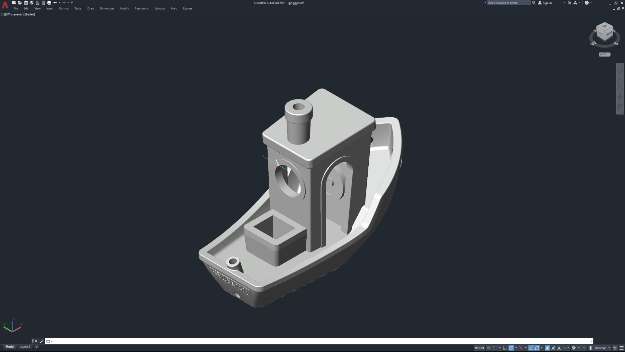
First things first.
Yes, you can absolutely use AutoCAD to create and export a 3D solid object to STL format.
The key thing here, which you need to understand, is that AutoCAD is fully capable of creating 3D printing models.
However, there are a few things you should think about.
AutoCAD is great for making mechanical parts, functional parts like brackets and enclosures, architectural models, and geometric shapes in general.
But if you want to make organic shapes or artistic models, Blender or ZBrush might be better options.
Understanding the 3D Printing Workflow
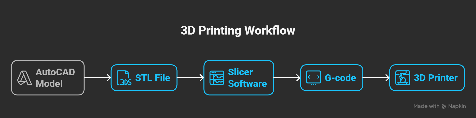
Before we dive into the nitty-gritty details, let’s understand how the workflow works. Your 3D printer will not directly understand the AutoCAD native DWG format.
Here’s the typical workflow:
AutoCAD model → STL file → Slicer software → G-code → 3D printer.
The STL (StereoLithography) file is a mesh version of your 3D model that has triangular faces.
Think of it as a surface made up of thousands of tiny triangles that are close to the smooth surfaces you started with.
The quality of this triangulation has a direct effect on how smooth or faceted your final print will look.
The slicer software you’re using (like Cura, PrusaSlicer, or Bambu Studio) then takes this STL file and converts it into G-code instructions that tell your printer exactly how to move and where to put material.
Creating Printable 3D Models in AutoCAD
Not all 3D geometry you create in AutoCAD will be suitable for 3D printing. You need to work with 3D solids, not surfaces and meshes.
Working with 3D Solids
Siqyrcy, CC BY-SA 4.0 , via Wikimedia Commons
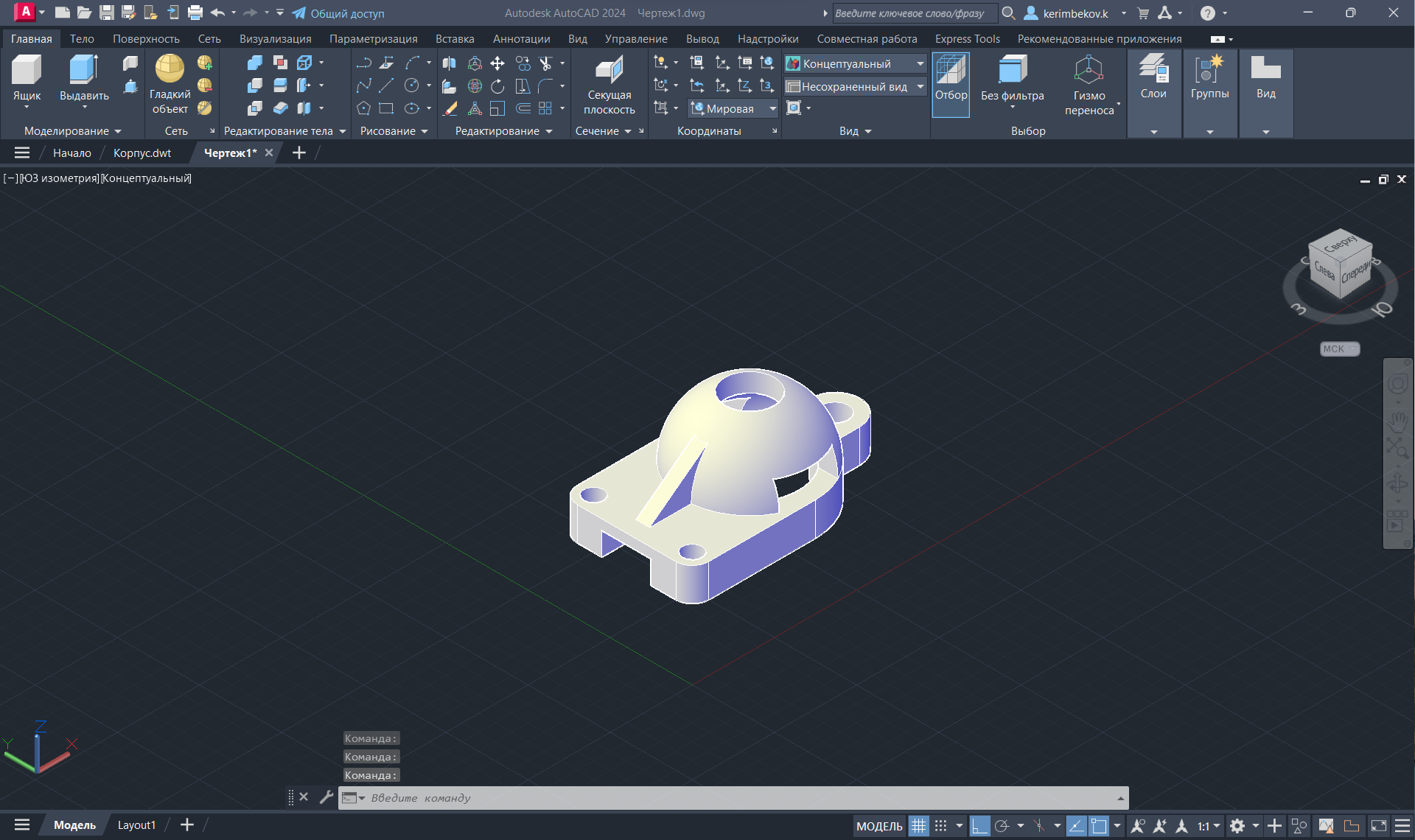
AutoCAD has several types of 3D objects, including surfaces, meshes, and solids.
For 3D printing, you must use 3D solids.
These are objects created using commands like BOX, CYLINDER, SPHERE, EXTRUDE, REVOLVE, LOFT, and SWEEP.
The reason here is that 3D solids represent complete, enclosed volumes with defined mass properties.
They’re “watertight” by default, meaning they don’t have any holes or gaps in the surface.
If you’re working with surfaces or meshes, you’ll need to convert them to solids first using the THICKEN command or by ensuring all surfaces form a completely closed boundary and then using SURFACETOSOLID.
Making Sure Your Model is Watertight
This is one of the most important concepts in 3D printing.
Your model must be watertight.
A watertight model means every edge is connected to exactly two faces with no gaps, holes, or overlapping surfaces.
Think of it like a water bottle. If there are any holes or gaps, water would leak out.
If there are gaps in your 3D model, the slicer software won’t be able to tell what’s inside and what’s outside, and your print will fail.
Your models should be watertight in AutoCAD if you use Boolean operators (UNION, SUBTRACT, INTERSECT) correctly when working with 3D solids.
You can use the CHECK command to check for problems with your solid objects.
Positioning Your Model
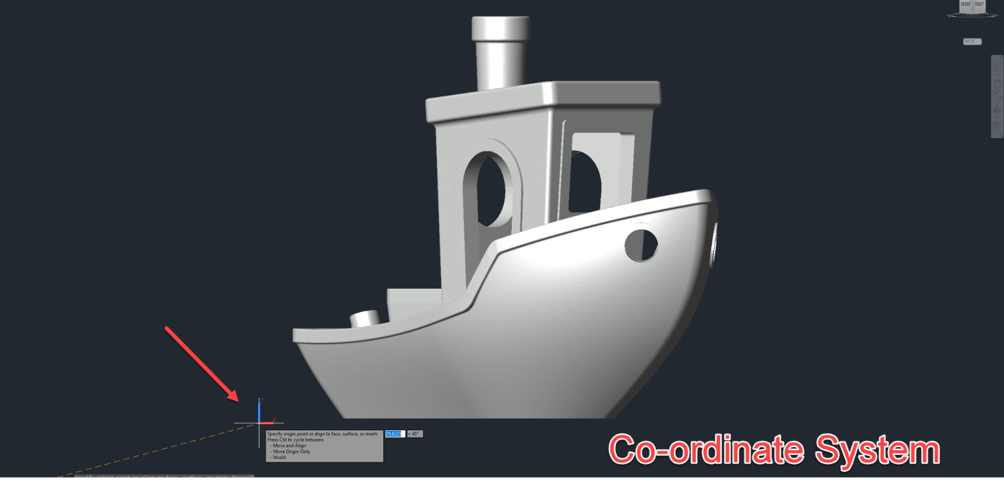
Before you export, you should also check that your model is in the right place in the coordinate system.
For your model to be correct, all of its parts must be in the positive XYZ octant, which means that all of its X, Y, and Z coordinates must be greater than zero.
If any part of your model goes into negative coordinates, the STL export might not work or give you results you didn’t expect.
If you need to, use the MOVE command to move your model.
It’s also a good idea to put your model so that the largest flat surface is at Z=0 (the XY plane).
When you import it into your slicer, this makes it easier to get it in the right position.
If you want to learn designing in 3D AutoCAD, then here is a series of 3D AutoCAD projects that you can try.
Exporting STL Files from AutoCAD
Let’s get started with the export process now. AutoCAD provides the STLOUT command specifically for exporting 3D solids to STL format.
Using the STLOUT command

Here’s the step-by-step process:
Type STLOUT at the command prompt and press Enter
Select your 3D solid(s) that you want to export (you can select multiple objects)
AutoCAD will ask if you want to create a binary STL file—type Y or press Enter to accept binary format (recommended)
In the Export Data dialog box, specify your file name and location
Click Save
That’s the basic process, but there’s more to getting quality exports.
Controlling Export Quality with FACETRES

The FACETRES system variable controls the resolution of your STL export. This is crucial for achieving smooth surfaces.
Type FACETRES at the command prompt. The default value is usually 0.5, but for 3D printing, you’ll want to increase this significantly.
I recommend setting FACETRES to a value between 2 and 10. Higher values create smoother surfaces with more triangles but also larger file sizes.
And after one point, the smoothness of objects becomes irrelevant in a manner.
For most prints, FACETRES=5 provides a good balance
For objects with lots of curves, go higher to FACETRES=10
For simple geometric objects, FACETRES=2 might be sufficient
The trade-off is file size and processing time versus smoothness.
Larger file size and too many triangles will also cause the slicer software to struggle processing the model.
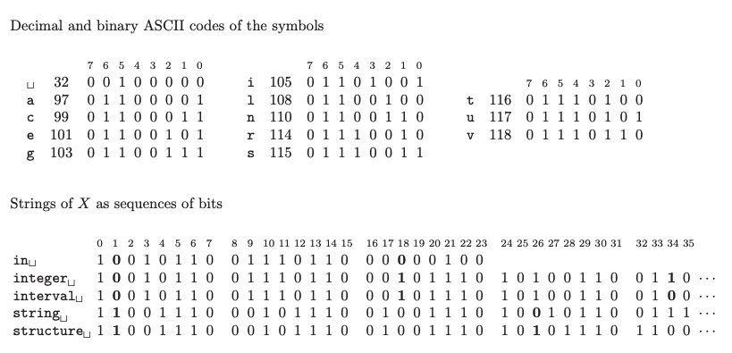
Binary vs ASCII Format
WikiLinuz, CC BY-SA 4.0 , via Wikimedia Commons
When exporting, you have two format options: binary and ASCII.
Binary STL files are significantly smaller (often 5-10 times smaller than ASCII files).
ASCII files are human-readable text files, which can be useful for debugging, but they’re inefficient.
Always choose binary unless you have a good reason to use ASCII format. Most modern slicers can easily work with binary STL files.
Common Problems with Exporting and How to Fix Them

Even if you model carefully, you might still have trouble exporting. Let’s fix the most common problems.
Holes or missing geometry
If some parts of your model don’t show up in the STL export, it’s likely that they are not solid.
Before you export, use the CHECK command on your objects. You need to fix the models with THICKEN or UNION or make the bad geometry again if CHECK finds any problems.
Sometimes surfaces that look closed actually have tiny gaps. Zoom in closely and check all edges are properly connected.
Faceted or Rough Surfaces
Increase FACETRES if the curved surfaces in the STL look too sharp or angular.
STL files use triangles to make curves look more like them, so more triangles make the shape look smoother.
However, as mentioned above, don’t go overboard. FACETRES values above 10 rarely provide noticeable improvement and just create huge files that might cause your slicer to struggle.
Scale Issues
This is a very common problem that catches people off guard.
AutoCAD doesn’t embed unit information in STL files. If you modeled in millimeters but your slicer interprets it as inches, your part will be 25.4 times larger than intended.
Use the UNITS command to check your units before exporting. Check to see if the dimensions of the STL match those of your original design when you import it into your slicer.
Most slicers let you change the size of the model if you need to, but it’s best to export it at the right size from the beginning.
Thread Details Not Exporting Properly
Threads are difficult and can be problematic to export in STL.
Fine threads might not export properly or appear smooth even with high FACETRES values because triangulation can’t always capture very fine details accurately.
If you want to make functional threads, you could make them a little bigger than they need to be and then cut the real threads with a tap and die after 3D printing.
Or, and this is probably the best way, you could use heat-set brass inserts.
These make thread connections that are stronger, better, and more reliable.
Preparing Your STL in Slicer Software
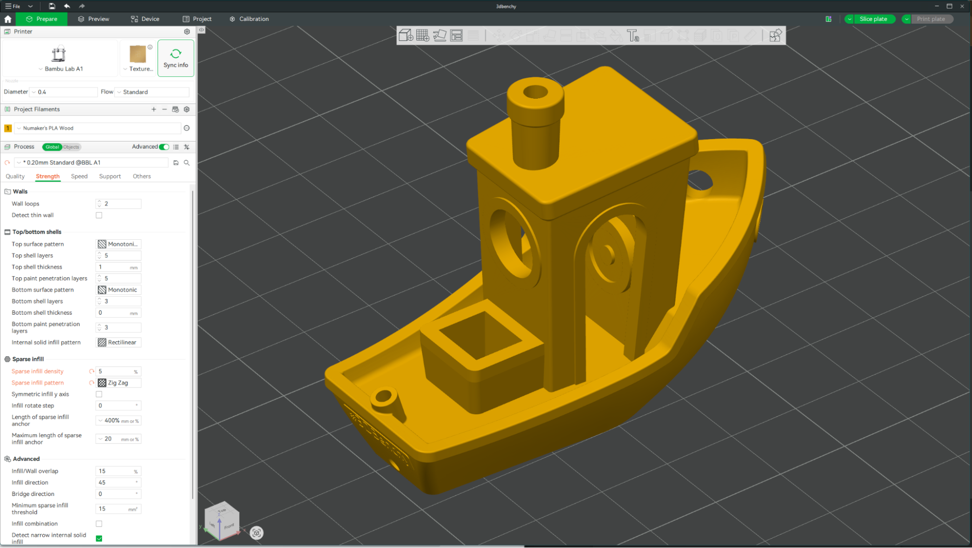
You will need to use the slicer software to get your exported STL file ready for 3D printing. We’ll just go over the main steps quickly.
Some of the most popular slicer software you can use are Ultimaker Cura (free and works with most printers), PrusaSlicer (excellent for detailed control), Bambu Studio (for Bambu Lab printers), and OrcaSlicer (a fork of Bambu Studio with extra features).
The first thing you should do after importing your STL is to look it over carefully.
Most slicers will automatically find and warn you about common problems, such as missing faces or normals that are upside down.
Check the model’s dimensions to make sure the scale is correct as well.
The orientation of the model is also very important.
To reduce the need for supports and improve bed adhesion, place your model so that the largest flat surface is on the print plate.
Set the height of your layers (0.2 mm is a good place to start), the density of the infill (20% for parts that don’t need to be strong), and the thickness of the walls (3–4 walls usually work well).
Finally, before you print, always use the preview feature to look through all the layers of your model.
Step-by-Step Workflow Summary
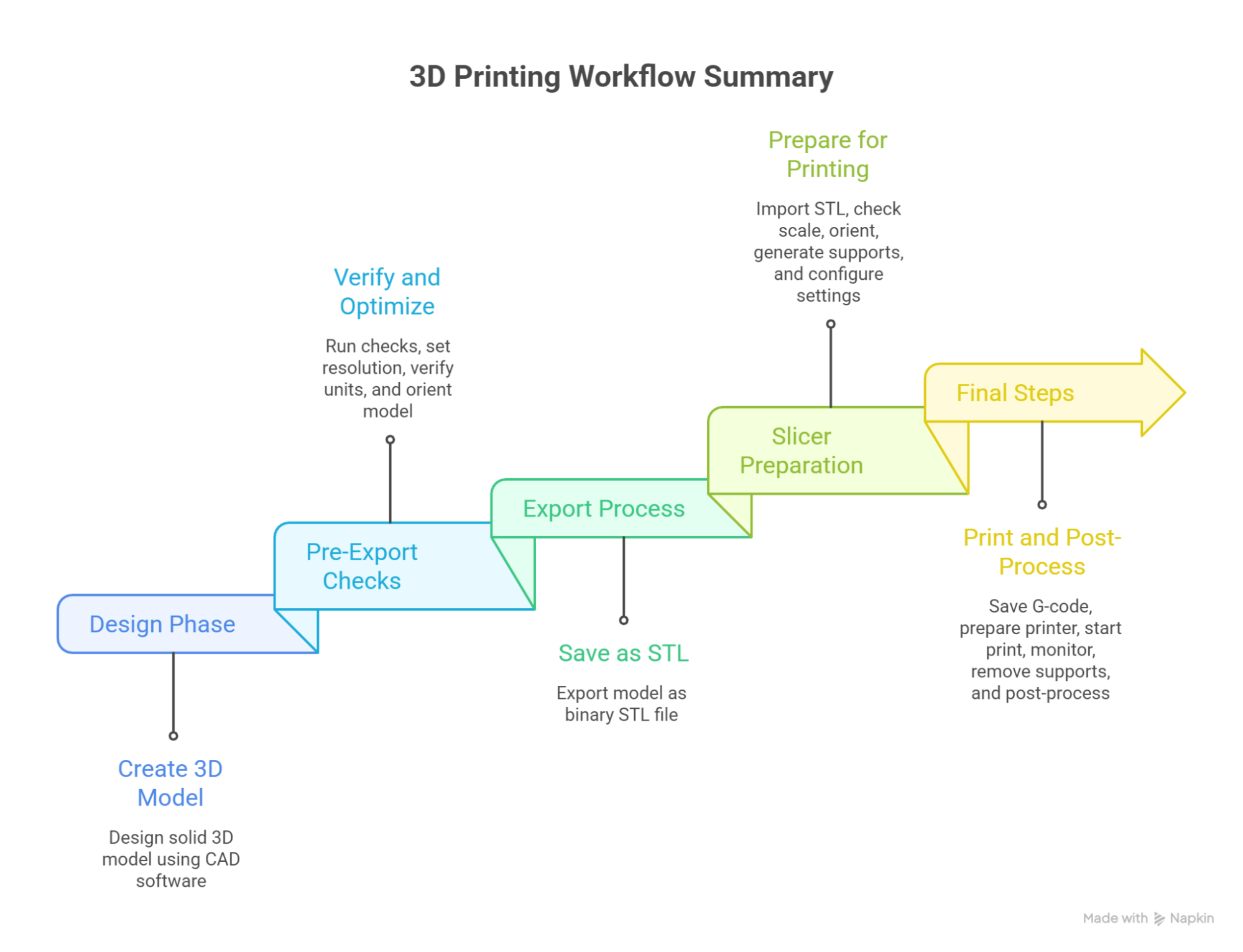
Now that we have an idea about the basic process, let me bring everything together into a clear workflow for ease of reference and so that you can follow better.
Design Phase:
a. Create your 3D model using 3D solid commands
b. Ensure all geometry is solid objects, not surfaces
c. Use Boolean operations to combine shapes properly
d. Position model in positive XYZ octant
e. Verify dimensions with MEASUREGEOM
Pre-Export Checks:
a. Run CHECK command on all solid objects
b. Set FACETRES (2-10 depending on complexity)
c. Verify drawing units with UNITS command
d. Position model for optimal printing orientation
Export Process:
a. Use STLOUT command
b. Select all objects to include
c. Choose binary format
d. Save the STL file
Slicer Preparation:
a. Import STL and check scale/dimensions
b. Inspect for import errors
c. Orient model optimally
d. Generate supports if needed
e. Configure print settings
f. Preview layer by layer
Final Steps
a. Save G-code to SD card or send to printer
b. Prepare print bed
c. Load correct filament
d. Start print and monitor first layers
e. Remove supports after printing
f. Post-process as needed
Summary
3D printing from AutoCAD is not rocket science and is something that is absolutely viable and can be very successful.
The most important thing is for you to know the basics of solids, how to set up the export settings, and how to set up the slicer.
Begin with easy things to boost your confidence.
As you get better at designing, you’ll start to know what designs will print well and what needs to be changed.
Don’t let early failures or the learning curve get you down.
You learn something important about design, how materials behave, and printer settings every time you make a mistake or a 3D print that doesn’t work.
If you keep practicing and are patient, you’ll be able to make prints that work every time.