AutoCAD scale factor chart
A scale factor is numerical ratio that compares drawing elements and items to its actual size in the real world. This helps in designing and drafting of…
A scale factor is numerical ratio that compares drawing elements and items to its actual size in the real world.
This helps in designing and drafting of complete models in a controlled environment like CAD, BIM software, or hand drafting before actualization in the real world.
For instances, the standard height of a Space X rocket, the Falcon series, standards at approximately 70 meters (230 feet); and the design was first done and simulated in a computer environment before its real-world replication to be the staggering technological marvel we all see today.
1. What is a scale factor chart and why is it so important?
A scale factor chart is then used to make the cross reference the different ratios between the size of what you draw the real-world object, instead of it being one option of ratios available, it has multiple rows for different design, paper sizes, disciplines, etc. expectations.
In AutoCAD designs we tend to draw in the real-world size of 1:1, meaning if an object in the real-world is 20 meters (65.6ft), then within the AutoCAD’s workspace, we will draw it with that same dimension.
Scaling only becomes relevant when you want to print or plot your drawing onto a sheet or when showing dimensions.
When placing the drawn CAD design onto a sheet using a viewport, you can define the specific scale factor you want for it, so that large footprint drawings can fit onto standard paper sizes that you have; or if you have call outs or detail views of an area in a drawing you can decide to scale it up to match the size that will be comfortable to interpret the drawing.
2. Standard CAD scale factors in drawings
When producing the sheets of the drawing in AutoCAD, there are certain scale factors that are generally used either in architecture or engineering to standardize the work output.
These standard scale factors are like 1:10, 1:20, 1:50, 1:100 and 1:200.
The above ratios mostly ensure that the drawing can still be printed on paper and maintain enough clarity to interpret the details of the design.
The interpretation of the ratio means as follows, for every 1 unit on the AutoCAD production drawing, it will represent the value on the right-hand side of the ratio as shown in the exhibition below.
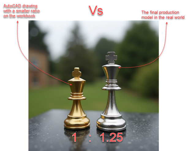
3. What the different kinds of scale factors are used for Architectural, and Engineering
Architectural scales focus on building footprints and sections with common rations like 1/8” =1’0 or 1:100, while engineering scales use more technical precision.
Civil Engineers working on site can use rations like 1:500, or when working on road designs 1:1000.
Mechanical and Electrical engineers who tend to work on smaller machine components can use ratios like 1:2 or in some cases when the parts are smaller in real life and need a design to view it, instead on the value on the right-hand side of the ration being bigger, it can be vice versa, like 20:1 meaning; 20 units length on the plotted paper is equal to 1 unit length of the actual model.
These types of scales where the model is smaller compared to the drawing is common in electronic engineering, nano-technology, micro and macro engineering, etc.
Some basic Scale Factor table:
1. Architectural Scale Factors use both Metric and Imperial units and are based on architectural drafting standards like ANSI/ASME Y14, or ISO 5455:
Architectural Metric
Drawing Scale | Meaning | AutoCAD Scale Factor | Standard Reference |
1:20 | Large details | 20 | ISO 5455 |
1:50 | Floor plans & sections | 50 | ISO 5455 |
1:100 | General building plans | 100 | ISO 5455 |
1:200 | Site/floor overviews | 200 | ISO 5455 |
1:500 | Site plans | 500 | ISO 5455 |
Architectural Imperial
Scale | Meaning | AutoCAD Scale Factor | Standard Reference |
1/8″ = 1′-0″ | Floor plans | 96 | ANSI/ASME Y14 |
1/4″ = 1′-0″ | Rooms/sections | 48 | ANSI/ASME Y14 |
1/2″ = 1′-0″ | Detailed rooms | 24 | ANSI/ASME Y14 |
1″ = 1′-0″ | Interior details | 12 | ANSI/ASME Y14 |
3″ = 1′-0″ | Joinery details | 4 | ANSI/ASME Y14 |
2. Mechanical Engineering Scale Factors generally use metric and are based on standards like the ISO 5455, ISO 128, or ASME Y14.3:
Drawing Scale | Usage | AutoCAD Scale Factor | Standards |
1:1 | Actual size | 1 | ISO 5455 / ASME Y14 |
1:2 | Assemblies | 2 | ISO 5455 |
1:5 | Components | 5 | ISO 5455 |
1:10 | Large objects | 10 | ISO 128 |
2:1 | Enlarged small parts | 0.5 | ISO 5455 |
5:1 | Very small components | 0.2 | ISO 5455 |
3. Electrical / MEP Engineering General Scale Factors generally use simplified scales for schematics and are based on standards like the IEC 61082, and IEEE Drafting Standards.
Drawing Scale | Usage | AutoCAD Scale Factor | Standard Reference |
1:10 | Conduit details | 10 | IEC 61082 |
1:20 | Cable routing | 20 | IEC 61082 |
1:50 | Power/lighting layouts | 50 | IEC 61082 |
1:100 | Entire floor electrical plans | 100 | IEC/ISO 5455 |
NTS (Not to Scale) | Schematics | Not Applicable | IEEE 315 |
4. Electronic Engineering Scale Factors generally use enlarged scales due to their circuits being small, and they refer to standards like the PCB / circuit design, IEC 60617, and ANSI Y32.2.
Scale | Usage | AutoCAD Scale Factor | Standards |
1:1 | PCB printing | 1 | IEC 60617 |
2:1 | Small boards | 0.5 | IEC 60617 |
5:1 | Chip level layouts | 0.2 | IEC 60617 |
10:1 | Micro circuitry | 0.1 | ANSI Y32.2 |
20:1 | High detail inspection | 0.05 | ANSI/IEEE |
5. Micro-engineering, nanotech & Scientific Drafting apply extreme enlargement scales for visualization, and generally refer to the ISO 5455 + discipline-specific requirements
Scale | Usage | AutoCAD Scale Factor | Standards |
50:1 | Microfluidic channels | 0.02 | Domain-specific (research labs) |
100:1 | MEMS components | 0.01 | Semiconductor drafting guidelines |
500:1 | Nanostructure visualization | 0.002 | ISO 5455 (adapted) |
1000:1 | Atomic layer structures | 0.001 | Nano-fabrication standards |
NTS | Concept sketches | Not applicable | Research guidelines |
6. Civil Engineering & Surveying Scale Factors generally rely on standard metric scales, and they generally refer to standards like ISO 5455, ISO 128, USGS, and NCS.
Scale | Usage | AutoCAD Scale Factor | Standards |
1:500 | Housing layouts | 500 | ISO 5455 |
1:1000 | Site plans | 1000 | ISO 128 |
1:2000 | Road corridors | 2000 | ISO/USGS |
1:5000 | GIS and mapping | 5000 | USGS/NCS |
Horizontal = 1:1000, Vertical = 1:100 | Profiles (roads/pipelines) | Cell | Civil 3D conventions |
4. What standards to consider when selecting scales?
Different countries adopt different standards of measurement; and also, different companies prefer different standards, but there are still well-known standards in the world that one can refer to like the ISO, ANSI, and architectural standards in US.
In fact, when dealing with certain kind of projects or bespoke clients, you will be required to implement a specific kind of scale, this can be observed with high end brands that use specific mold to come up with models, take for instance an iPhone or a Samsung phone, they have specific mold to design the outer shell of the phone, this can allegedly lead to their own model designers to use custom made scales to meet the mold requirements.
Selecting your scale is determined with the type of project you are working on, the level of detail required to be displayed, and the sheet of production you will adopt for the final plotting.
Agreeing on the scale standard that will be used in the project, will make it seamless for collaboration between the teams on the project, from the design team to the construction team.
Below is a table showing the different standards, and where each is most practical for its application:
Standard Code | Description | Industry |
ISO 5455 | Technical drawing: Scales | Architecture, Mechanical, Civil |
ISO 128 | Technical drawing: General principles | Engineering drawings |
ASME Y14 Series | US mechanical/architectural drafting | Architecture, Mechanical |
IEC 61082 | Electrical documentation | Electrical/MEP |
IEC 60617 | Electronic symbols and drafting | Electronics |
IEEE 315 / ANSI Y32.2 | Electrical/electronic graphic symbols | Electronics/Electrical |
NCS (National CAD Standard) | US CAD standards | Architecture, MEP, Civil |
USGS Mapping Standards | Surveying & mapping | Civil, GIS |
5. Annotative scales and why they are so important
Annotative scales allow for sizes of text fonts, symbols and dimensions to be automatically adjusted based on the scale of the viewport selected.
This comes in handy when placing the final deign drawing on paper as you don’t need to manually adjust the annotations made on every sheet in the even the sheet paper is changes.
The Annotative scale ensures consistency in the readability across all scales and eliminates the nightmare of fonts or symbols looking too small of ginormous on a drawing that the scale is changed.
6. Frequently Asked Questions:
What is a Fit Scale in AutoCAD?
A fit scale allows for automatic adjustment of the drawing to fit within a sheet of paper without selecting a specific ratio with the AutoCAD environment.
What is Scale by Reference in AutoCAD?
Scale by Reference allows you to scale drawing objects within the workspace by referencing it between two known points, and it is commonly used in importing scanned drawings with known dimensions into the AutoCAD environment and scaling it correctly.
What is Absolute scale factor in AutoCAD?
Absolute scale factor is the specific numerical value you input into the AutoCAD software when scaling.
It is the communication from you the user to the software oh how it should treat the item of interest, by either scaling up, or scaling down.
Conclusion:
Most AutoCAD beginners face issues like the text’s fonts being too big, or too small, printing illegible drawings, as they are too big or too small, or even mismatch between scales for different models.
This are all contributed by the selection of the wrong scale factor or not taking the time to understand what scaling is all about.
It is important to be vigilant when working on drawing with different or mixed units like metric and imperial.
Let me know what think the scale factor was used to design the tallest building in the world or the smallest nano-tech existing on earth, I can imagine the engineers agreeing on which scale factor to be adopted and the rationale behind it.