Layer naming standards for your CAD drawing (complete details)
What is a CAD layer? CAD layer is a digital container, with a user given name, that helps group common drawing attributes and properties in one logical…
What is a CAD layer?
CAD layer is a digital container, with a user given name, that helps group common drawing attributes and properties in one logical section that is easy to use and manage the drawing information.
Why are CAD layers important?
CAD layers can be thought of like invisible workspaces stacked on top of each other, each stack holding certain amount of information that acts independent from all the other stacks.
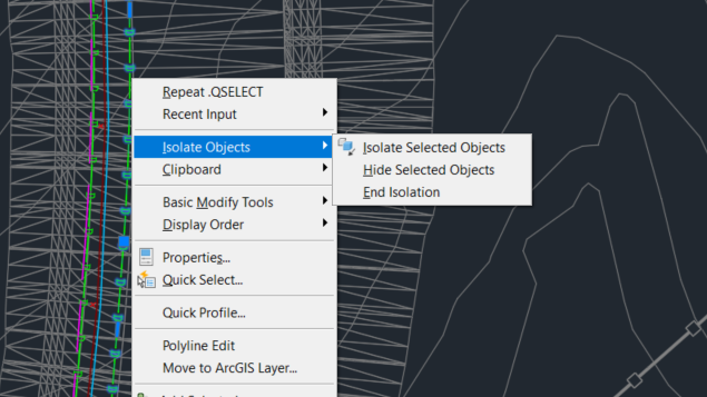
This stacking capability allows for hiding other stacks and solely focusing on one, or changing information on one stack without affecting the others, this can be achieved by using layer names are quick selection measure or isolate/ hide layers dependent on the shared properties.
Below is an example of the fly out menu available in AutoCAD Civil 3D in the right click menu.
CAD Layers facilitate the customization of the layer line styles and groups to represent different visuals as well as architectural, engineering and construction information.
In collaboration works CAD layers are used to assign different people or teams to different sections of the drawing, think about it as worksets which lead to minimized clashing and clear responsibility scopes in projects.
CAD Layers help in providing accurate, consistent and quality information by applying different line colours, line types, line weights, etc.
This makes drawing elements looks standardized throughout. (avoiding cases where the same members in the same drawing are having different visual representation)
CAD Layers can be used to control plotting options by deciding which layers should be included or omitted from the plot making the deliverables of the user simplified, for example construction drawings for tendering don’t need all fine details but only general information.
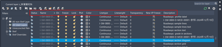
Below is an example of the options available in AutoCAD Civil 3D in the Layer Properties Manager menu.
When working on large project designs and heavily loaded data CAD files, CAD layers help in fragmenting the drawing into workable data sizes and using external referencing to the required layers.
This is especially common in civil projects that tend to have designs spanning a vast area, or in Mechanical Projects with complex systems and detailing.
What is Layer 0, and when do you use it?
I know you have seen this in your basic CAD software, like AutoCAD, when you have launched a completely new drawing and you look at the Layers properties panel, you usually find Layer 0.

Layer 0 is the default and always present layer in most common DWG based CAD systems, it facilitates for quick drafting when the software is launched, or importing files like images and PDFs instantaneously, without the need of having to first create a layer.
But, when it comes to a basic standard design, Layer 0 should be used sparingly while the designer should create other CAD layers that meet the purpose of the design requirements.
Layer 0 in CAD can be used for creating objects and blocks in CAD software as items made with Layer 0, if brought into a CAD workspace environment with other layers, the items automatically pick the layer properties of the specified layer.
This is not the norm if the objects and blocks are made from different layers.
But, when it comes to drawing regular model geometry, Layer 0 should not be used, as it removes the ability to control the geometry independently, preventing you from using features like isolating, hiding, colour and line weight customizations, or plotting using the layer capabilities.
Standard CAD layer sets in drawings and why use them?
Standard CAD layer sets are a predefined group of layer names and organizational rules within the CAD environment that it helps in maintaining consistency, reducing confusion and complying to the existing acceptable industry standards.
The layer sets support different disciplines like Architectural, Mechanical, Electrical, Plumbing, Civil and Structural, making it easy to work on the different disciplines independently, making the use of Xrefs or Clash detection easier.
Majority of the time, these Standard layer sets are usually embedded in template files making it easy for reusing, as each new drawing created using the template with the layer set will start with the agreed colours, line weights, line types, plot style, etc.
These Standard layer sets are more common in complex CAD program like AutoCAD Civil 3D, AutoCAD Architecture, AutoCAD Plant 3D, etc. that uses a couple of layers to represent the different information on the designs.
Layer sets make the transition of the CAD file into 3D or even BIM seamless as data can be incorporated into the different layers depending with what is required.
What the layers stand for (structured layer fields and examples)
Now that you understand what Standard CAD layer sets are, the question is how are the made and what governs the making or modification of the sets.
Layers naming follow a standard that in in line with the multidiscipline or multifield nature and structure of projects, so that if anyone was to open a drawing,
they could immediately understand what each layer was met for and what data and properties are contained.
The Standard layer set system follows a code system with several parts, each part communicating different information to the CAD users.
According to the United States National CAD Standard (NCS), the naming convection is broken down into five main distinct fields namely, Discipline and Designator, Major Group, Minor Group, Modifier or Presentation, and Status.
The NCS, which is the most commonly used standard for layer naming, ensures for consistency and clarity across drawing and projects.
The first field, discipline and designator, identifies the roles and such as A for architecture, C for Civil, S for Structural, P for Piping, M for Mechanical, etc.
The second field, Major Group, gets more specific about the first fields information, like the Walls under the Architectural discipline, so the name “WALL” will be added to the layer name.
The third field, Minor Group, adds more information or sub classification of the items described under the Major group, for example, INT to represent the Interior nature of the wall.
The fourth field, Modifier or Presentation, communicates on how the information is represented such as is it linework, Hatches, etc., if the layer is a line, then the name “LINE” will be added to the layer name.
The fifth field, Status, informs about the phase of the element or the project, for example if members in the project are for demolition, the code name “DEMO” can be affixed to the layer name to represent his case.
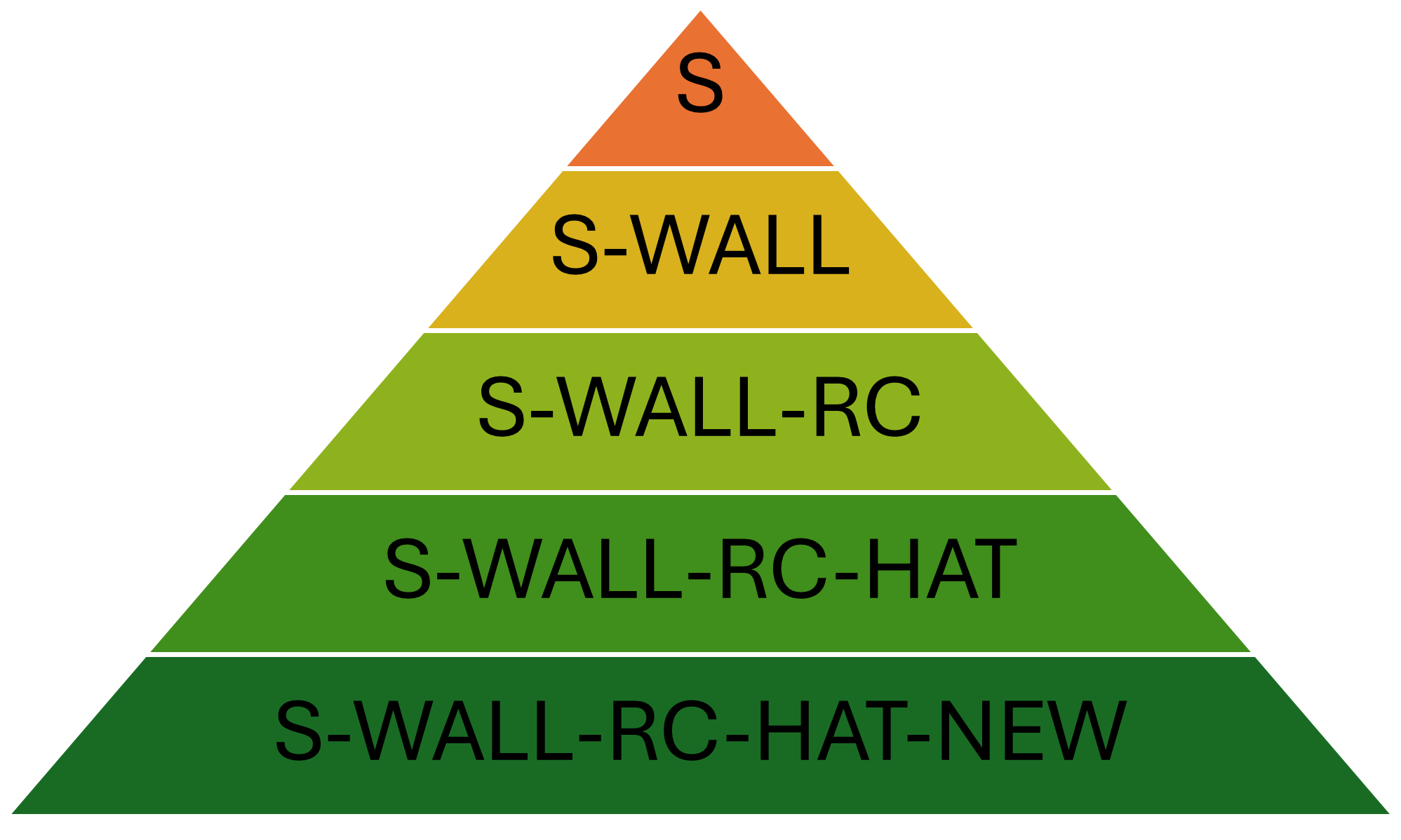
The below table shows the main fields in a typical CAD layering naming standards and how it is built up.
Field / Group | Purpose | Common Codes / Values | Example Layer Name | Explanation of Example |
|---|---|---|---|---|
1. Discipline or Designator | Identifies the discipline or trade creating the element. | A = Architecture, C = Civil, S = Structural, M = Mechanical, E = Electrical | S | This layer is part of the Structural discipline. |
2. Major Group | Describes the primary building system or element. | WALL, DOOR, COLUMN, ROOF, SITE | S-WALL | Structural layer for all walls. |
3. Minor Group | Adds more detail or sub-classification. | EXT = Exterior, INT = Interior, GL = Glass, STL = Steel, RC =Reinforced Concrete | S-WALL-RC | Structural walls that are Reinforced Concrete. |
4. Presentation or Modifier | Indicates how the information is represented or its content type. | LIN = Linework, HAT = Hatch, TXT = Text, DIM = Dimensions | S-WALL-RC-HAT | Reinforced Concrete structural walls, shown as Hatch. |
5. Status or Phase | Shows the project phase or element status. | NEW = New work, EX = Existing, DEMO = Demolition | S-WALL-RC-HAT-NEW | New Reinforced Concrete structural walls, shown as Hatch. |
The full Build up is hierarchical, with each level adding more information to the layer.
There are still other CAD layer standards that can be used to relay the same information like the:
ISO 13567, which is an international standard for organizing layers used out of the US, the standards are similar, but may be separated using hyphens or underscores, for example S—WALL—RC–HAT—N.
BS 1192 (UK), which is a British standard for construction information management, is usually integrated with Building Information Modelling (BIM) work flows and still follows the fields in the NCS.
AIA CAD Layer Guidelines which was the basis of the NCS in the US, but can still be used,
Company and User specific standards that are specific to the nature of the project or requirement.
List of common layers
For Civil 3D Users, out of the 217 layers in a new drawing standard AutoDesk “acadiso” template, below is list of the layer name and its description:
Name | Description |
0 | 0 |
C-ANNO-TABL | Civil: Table |
C-ANNO-TABL-PATT | Civil: Table Hatch |
C-ANNO-TABL-TEXT | Civil: Table Text |
C-ESMT-ROAD | Easements: roadway |
C-PROP-BNDY | Property: boundary |
C-PROP-BRNG | Property: bearing |
C-ROAD-ASSM | Roadways: assemblies and subassemblies |
C-ROAD-ASSM-BLIN | Roadways: assembly baseline |
C-ROAD-ASSM-OFFS | Roadways: assembly offset |
C-ROAD-ASSM-TEXT | Roadways: assembly text |
C-ROAD-BRNG | Roadways: bearings |
C-ROAD-CNTR | Roadways: centerline |
C-ROAD-CNTR-N | Roadways: centerline, NEW |
C-ROAD-CORR | Roadways: corridor |
Others layer names from various disciplines, include but are not limited to:
Discipline | Layer examples: |
Architectural | A-WALL-EXT-LN, A-DOOR-INT-TXT, A-FURN-GEN-HAT, A-GLAZ-PAN-LN, A-PLN-DIM. |
Structural | S-CLM-BEAM-LN, S-FOUND-FOOT-HAT, S-REBAR-TXT, S-GRID-LN, S-SECTION-MRK. |
MEP | M-HVAC-DUCT-LN, E-LGT-FIX-TXT, P-WTR-PIPE-LN, M-PLMB-FIX-HAT, M-SYMB-GEN. |
Civil | C-TOPO-CTR-LN, C-ROAD-EDGE-LN, C-EXIST-PT, C-SURF-CNTR, C-GRID-COORD. |
Frequently Asked Questions:
What is Layer mapping in AutoCAD?
When importing a PDF, or older and third party CAD files, many are the times that the layers won’t match your standards as some can come in with the PDF name like “PDF-Layer-Furniture-1”, or something vague like “Layer 1” or “Blocks” etc.
This can be resolved by mapping the non-standard layers to your templates’ standards layers, either manually or automatically.
Software like AutoCAD, have the mapping feature called Layer translator and is located under the Manage tab, under the CAD Standards Panel.
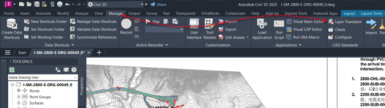
You can also save your mapping settings as a file to make the layer translation faster.
Do Layer naming standards apply in BIM workflows (Revit, Civil 3D, etc.)?
For BIM tools like Revit, it uses families and categories instead of the basic CAD layering standards to represent different design components like columns, beams, slabs, etc.
But, when exporting drawings from Revit to CAD programs, you can use the Layer mapping settings available in most CAD software to integrate the CAD layers generated from Revit with your CAD Layer Standard.
For BIM tools like Civil 3D, the CAD Layer Standards apply as Civil 3D relies on objects layers and styles to represent different design components like roads, highways, etc.
A pro tip would be to establish a cross mapping table that you or your team can refer to especially when working with CAD designs to ensure streamlined working, consistency and efficiency of the final work products.
Does Layer naming affect my final deliverables?
Yes, the layer naming you choose can affect your final deliverables like what your client, contractors, or sub contractor will see, as for different disciplines or phases in the project, like construction, demolition, tendering, as built, etc. you can choose to include or hide specific layers like fine detail dimension, notes, etc., using the layer states or filters.
Before submitting your final drawings, always perform your Quality Assurance checks by purging unused layers, auditing the drawing for compliance and validate it against the client and national standards to avoid having a legal or contractual risk especially for government or large infrastructure projects.
The good thing is that most of the CAD tools offer these provisions out of the box, for example, for AutoCAD Civil 3D, under the manage tab, the CAD Standards and Styles panels will greatly help automate these processes.

Conclusion
CAD Layer Standards are truly important for any CAD user, and need to be understood to get the final deliverables for clients right, as well as making the design process seamless and standardized leading to minimized design confusion or vagueness.
Let me know in the comment section below, do you use CAD Layer Standards for your designs and what else do you think I missed out?