Roofs in Revit Complete Step-by-Step Process
Revit is a powerful BIM (Building Information Modelling) software tool that enables designers, engineers, and architects to create building models with…
Revit is a powerful BIM (Building Information Modelling) software tool that enables designers, engineers, and architects to create building models with precise, detailed, and parametric roof structures.
In this project-based article, I will take you through the complete step-by-step process of creating various roof types, from basic designs such as gable and hipped roofs to complex ones like M-Roof and Moonlight roofs.
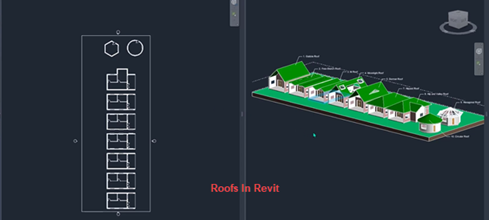
Additionally, I will take you through the integration of the roof models into Lumion for enhanced visualization.
Here is a video version of the article for a better visual walkthrough.
Gable Roof Design
A gable roof is a pitched roof with two sloping sides.
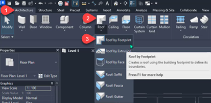
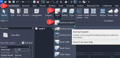
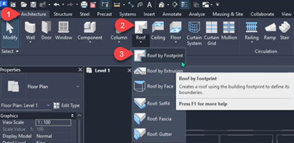
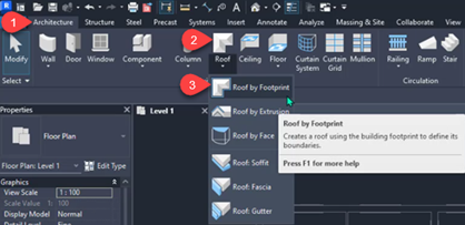
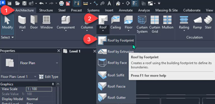
To create it in Revit, navigate to the Architecture tab and select Roof under the Build panel.
Under the roof option, select “Roof by Footprint to outline the roof boundary.
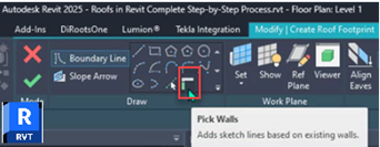
In the Modify| Create Roof Footprint panel, use the Pick Walls or Pick Lines options to outline the roof in the plan view.
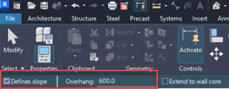
Depending on the type of design, you could tweak the settings defining the overhang of 600mm and setting the slope.
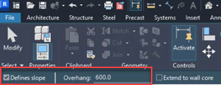
The overhang typically extends the sides of the roof to prevent water from running on the wall sides.
In this example, the overhang is set to zero with a slope of 45 degrees.

Once the footprint is completed, finalize the design by clicking Finish Edit Mode.
The roof will be as depicted below in 3D.
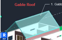
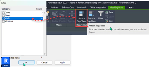
To achieve a complete model structure, attach the walls to the roof by selecting all walls, using the Attach Top/Base tool, and specify the roof as the attachment point.
Free Sketch Roof Design
A free sketch roof is a custom roof designed using freeform sketching.
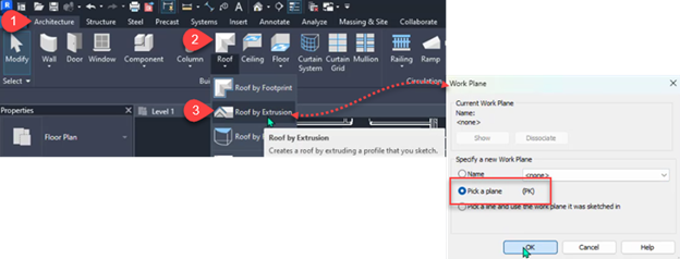
Start by selecting Roof by Extrusion from the Build panel in the Architecture tab.
In the Work Plane floating window, enable Pick a Plane to select a plane to define the reference for sketching the roof.
Select the wall panel, and in the Roof Reference Level and Offset floating window, set the roof’s Level and Offset.
Sketch the roof on your reference plane using the Spline drawing tool in the Modify | Create Extrusion Roof Profile panel.
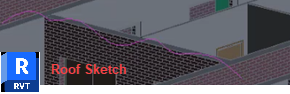
Finalize the roof by clicking Finish Edit Mode, and in the Properties menu, adjust the roof dimensions using the Extrusion Start and End settings.
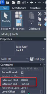
Extend the roof over the building model using the grip markers on the roof as shown below or input an offset of 250mm to ensure proper roof coverage.
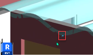
As with the other type of roof, attach the walls to the roof, use the Attach Top/Base tool option and select the roof as the attachment point.
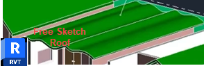
M-Roof Design
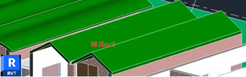
This type of roof consists of two connected gable roofs.
Since in Revit, you can only have one distinct roof sketch in a single roof, you will only sketch on one half of the roof area as shown in the exhibit below.
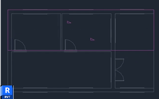
First, create one gable roof, then in the plan view, copy it and align it with the other half, ensuring that the two roof sketches are equidistant.
Define slopes only on the longer edges of the roof.
This type of roof will need to have a gutter to manage the water drainage since this design features a valley at the centre.
To do so, navigate to the Architecture tab, and under the Build panel, select the Roof Gutter option.
Select the placement line to position the gutter.
This can be visibly seen in the 3D view.
Finally, attach the walls to the roof using the Attach Top/Base tool option then select your roof as an attachment point.
Moonlight Roof Design
This can be any type of roof with integrated skylights for natural lighting.
Begin by creating a roof by footprint using a rectangle as a drawing tool option and with slopes on the longer edges.
Upon selecting Finish Edit Mode, you will notice that you have created a gable roof.
Next, navigate to the Architecture tab, under the Opening panel select By Face to create an opening on the roof surface.
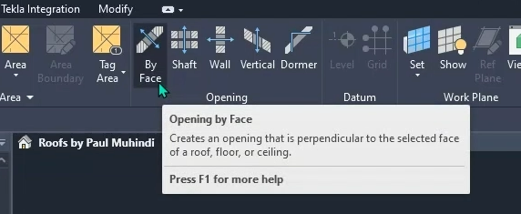
Pick and select one face of the roof.
Using the rectangle drawing tool, sketch out the opening on the roof as shown in the exhibit below.
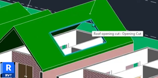
Alternatively, you can insert a pre-loaded window to create the moonlight effect.
Finalize by attaching the walls to the roof by using the Attach Top/Base tool option.
Dormer Roof Design
A dormer roof consists of dormer windows for added space and ventilation.
First, create a gable roof.
To create the dormer roof, sketch it out using the Roof by Footprint option and a rectangle drawing option on a section on the parent roof.
Define the slopes only on the shorter edges of the dormer roof.
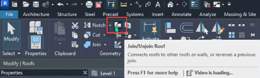
To integrate the dormer roof with the main roof, select the dormer roof and use the Join/Unjoin tool under the Geometry panel as shown in the exhibit below.
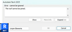
If you get a warning that the two roofs are not joining as shown below, unjoin them and reposition the dormer roof so that it aligns with the main roof.
In 3D switch to the Wireframe display to select one face end of the dormer roof where it will attach to the parent roof.
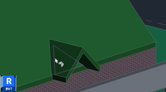
To create an opening for the dormer, navigate to the Architecture tab, and under the Opening panel, select the Dormer option, then outline the area for the cut.
Trim the lines to ensure an enclosed triangle shape in the area you want to create the opening as shown in the exhibit below.
In the opening created, you can now add a curtain wall or a window.
In this example, I will bring in a curtain wall in that opening.
To do so, navigate to the Architecture tab and under the Build panel, select Wall and choose the Wall: Architectural.
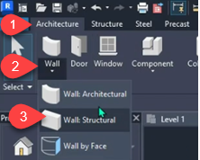
Choose the Curtain Wall-Exterior Glazing and set the Base Constraint to the level of your walls.
Do not define the top constraints because you will have to pick the dormer roof lines to set your curtain wall top level.
So once you have drawn it on the 2D plan, you will select it and click on Edit Profile to pick the inner dormer roof walls to ensure the curtain wall takes the shape of the roof.
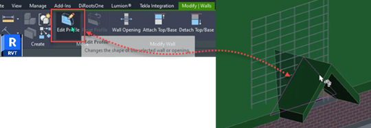
Finalize by attaching the walls to the roof using the Attach Top/Base tool.
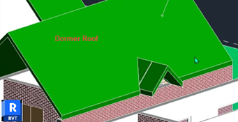
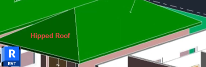
Hipped Roof
This is a roof with slopes on all sides.
To create this, use the Roof by Footprint option and define the roof boundary using the rectangle drawing option.
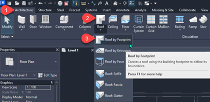
In this example, the roof will be placed with an eave offset of 600 mm, and the slopes defined on all the roof sides.
Ensure the base offset is set to zero.
Once the roof is complete, attach the walls to the roof, select all the walls, then select Attach Top/Base tool.
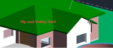
Hip and Valley Roof Design
This is a complex roof with intersecting hipped sections.
To create this, use the Roof by Footprint and use the Pick Walls drawing option to outline the roof.
Define the roof slopes on all sides and an overhang set as 600mm.
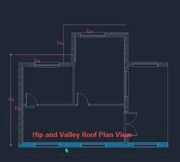
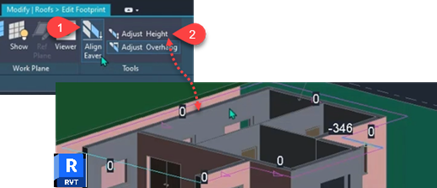
To get a better and seamless roof intersection, you can adjust the eave height by selecting the roof, navigating to the Tools panel clicking on the Align Eaves option then proceeding to select Adjust Height.
Finalize by attaching the walls to the roof by using the Attach Top/Base tool.
Hexagonal Roof Design
Commonly used in pavilions and gazebos, this is a six-sided roof that is created using the Roof by Footprint option.
Outline the roof shape using the Hexagon drawing option as shown below or by the Picking Walls option.
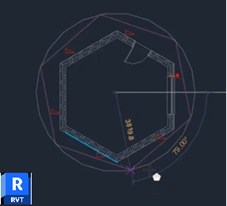
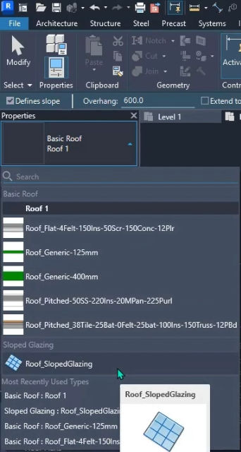
Apply an overhang of 600mm and assign a material such as a roof curtain wall.
You can also assign a material to the roof.
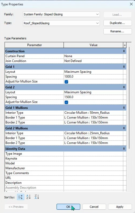
To modify the roof curtain wall properties, click on the Edit Type in the Properties menu then add mullions as shown below.
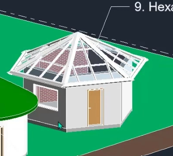
Select the walls and use the Attach Top/Base tool to form a complete structure as shown below.
Circular Roof Design
A circular roof follows the same procedure as a hexagonal roof but the roof boundary is outlined using a circular drawing tool.
Alternatively, use the Pick Walls option to outline the roof boundary.
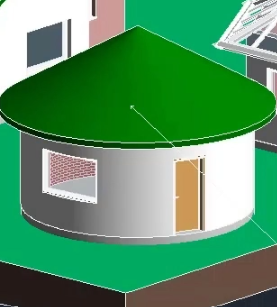
Finalize the model by attaching walls to the roof using the Attach Top/Base tool.
Integrating models in Lumion (third-party plugin)
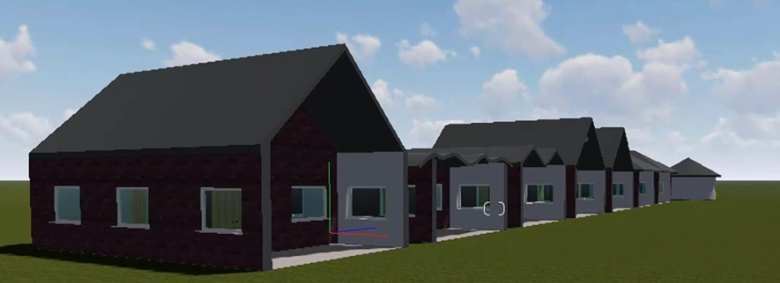
To enhance visualization, Revit models can be seamlessly integrated into Lumion.
Under the Lumion Tab in Revit, select Live Sync to synchronize the models, allowing visualization in Lumion’s rendering environment as shown in the exhibits below.


Frequently Asked Questions
Here are some of the frequently asked questions from our students.
How do I modify the roof after modelling it?
Roofs can be modified by selecting them and using the Edit Profile or Edit Footprint options to adjust the roof boundary, slopes and overhangs.
How can I create roof overhangs at different dimensions on each side?
While sketching the roof footprint, manually set different overhang values for each side in the Properties Panel.
Can one create a multi-level roof within the same building model?
Yes, it is possible.
Create separate Roof by Footprint elements for each level.
Adjust the Base Level and Offset values in the Properties menu then finalize by joining roofs by using the Join/Unjoin Roof tool to connect overlapping sections.
Summary
This article provides a detailed walkthrough for creating various roof types in Revit, including gable, hipped, dormer and complex designs such as M-Roof and Moonlight roofs.
It covers essential steps, from defining footprints and slopes to adding structural elements like gutters and skylights.
Additionally, it explains how to integrate models into Lumion for better visualization.
By following these step-by-step instructions, you can efficiently design accurate and visually appealing roofs in Revit, ensuring a well-structured architectural model.
If you have questions drop them in the comments section down below.