All about lines in Revit including Detail and Model Line
Lines in Revit are crucial in designing architectural, structural, or MEP projects, they are the foundation of 2D and 3D designs. Lines can be used to…
Lines in Revit are crucial in designing architectural, structural, or MEP projects, they are the foundation of 2D and 3D designs.
Lines can be used to define geometry, outline structures, and add annotations to improve the project clarity.
In this article you will understand the uses of lines (model and detail line), learn how to create and modify both detail and model lines.
For a more detailed visual walkthrough, here is a video version of the article.
Model Lines in Revit
Model lines are elements that are visible in the entire model and all views, that is, elevations, 3D models and 2D floor plans.
Model lines play a role in the physical representation of a project.
To create model lines, navigate to the Architecture tab, select Model Line under the Model panel, or use the keyboard shortcut LI to activate the Model Line command.
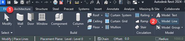
Under the Draw panel, choose Straight line as the shape to draw the model line.
Navigate to the Options bar and check the box in the Chain option.
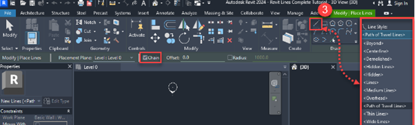
This keeps the line tool active, allowing you to continue drawing from the last end point.
Choose your preferred Line Style and the correct Work Plane for your model line to ensure proper orientation.
Detail Lines in Revit
Unlike model lines, detail lines are only view-specific, and often used in 2D drawings or documentation purposes like annotations or view-specific construction details.
Interestingly enough, detail lines cannot be drawn in the 3D model in Revit.
To create Detail lines, navigate to the Annotate tab and select the Detail Line.
Draw these as you would a model line though they will not display in other views.
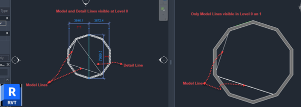
Difference between Detail Lines and Model Lines
The key difference between Revit’s Model lines and detail lines lies in their scope.
Model lines are part of your 3D model and are visible across your multiple views, while detail lines are view-specific and serve more for annotation purposes.
For example, to represent a physical object in your drawing, for instance, a beam’s centerline, use model lines so that you can visualize the beam’s centerline in all views.
Use detail lines in your specific view to provide additional information to the model geometry, such as, annotating/highlighting load paths, and outlining regions/zones like openings or slab edges.
Converting Detail Lines to Model Lines and vice versa
Revit is quite integrated in such a way that it allows seamless conversion between model and detail lines, avoiding redrawing.
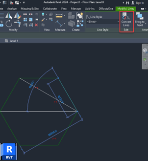
To convert a line, select the line, under the Modify tab and select the Convert Lines tool for the same action.
Different Line Styles and Types in Revit
Some of the predefined line styles in Revit, include solid, dashed, or centerline, each serving different purposes in your project documentation.
Navigate to the Manage tab, select Object Styles, and under the Lines tab, you can modify the visual appearance of different line types by adjusting the thickness and color.
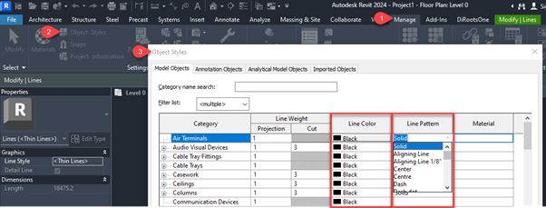
Alternatively, if you have already created your lines within your model, simply select on your line(s), and in the Modify tab, under the Line Style panel, choose the one that you prefer.
These visual distinctions help in differentiating elements in your project drawings for easier interpretation.
Creating Custom Lines in Revit
The good thing about Revit is that you are not just limited to the pre-build lines that come with the software.
If the predefined styles do not suit your project needs, you can create your custom line types.
Navigate to the Manage tab; under the Additional Settings, select Line Styles, and then click New option in the New Subcategory dialog.
Name the line, in this case we called it SourceCAD, customize the lines’ weight/thickness, colour, and pattern to suit your project design needs, then hit on Apply to save changes.
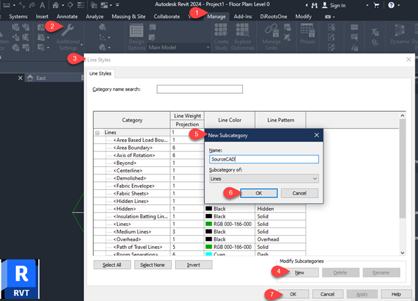
So, once you go back to your model and you want to draw your detail or model lines, you can find your custom-made line type under the Line Style drop-down list.
Adjusting Line View Range
Adjusting your line view range is very useful when working with multi-level buildings or varying elevations.
To do this, under Properties menu, click on View Range, and adjust the cut plane to control which lines appear in your view.
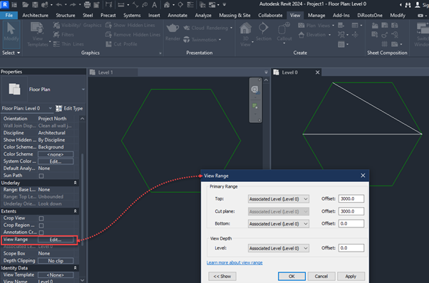
Alternatively, under the Properties menu, select Extents, and edit your view range.
How to Hide and Unhide Lines in Revit
Hiding either model or detail line helps to clean up a view and focus on a particular area of the model.
Select the line you want to hide, right-click, choose Hide in View and then click on Element option.
To unhide, go to the Reveal Hidden Elements icon in the View Control bar and select the lines to unhide element.
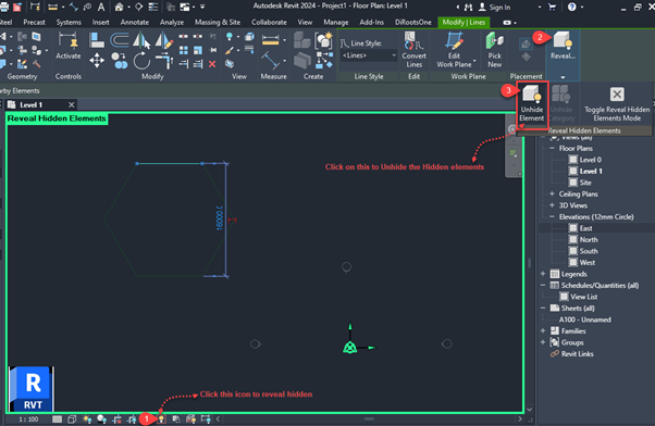
Alternatively, navigate to Properties menu and select Visibility/Graphics Override then click on Edit to check or uncheck your preferred line to override.
Alternatively, using the keyboard shortcut EH, you will achieve the same results with less click and steps.
Simply select the item that you want to hide and key in HW on your keyboard.
To view or return the hidden lines to your current view, you can either change your visibility settings under the Visibility/ GraphicsOverrides panel, or use the Reveal Hidden Elements options to bring back the lines to your view.
Copy, Paste, and Delete Model Lines in Different Elevations
To enable quick duplication of the lines across multiple levels, select the model line, press Ctrl + C on your keyboard to copy or navigate to Modify/Lines, select Copy, and then paste it in the desired elevation or level view.
If you want to delete either your Model or Detail lines, simply select the line and press the Delete on your keyboard, or use the DE keyboard command.
Revit Line Weights
Line Weights refer to the thickness of a line.
In Object Styles, you can adjust the line weight thickness values of the Projection Lines and Cut Lines for model objects, annotation objects, analytical model objects and imported objects.
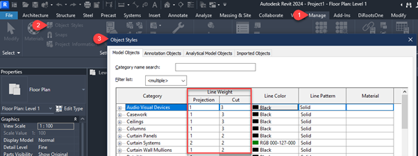
Projection Lines are lines that indicate objects that are shown in the 3D view.
Cut Lines are used when an object intersects the cut plane of the 3D view and are thicker in size as compared to projection lines.
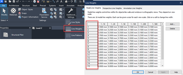
Under Additional Settings, Line Weights are categorized into;
Model Lines weights:
These are view-scale dependent lines that are directly related to the physical elements within the model, such as walls, windows, beams and they affect the visual appearance of lines in views such as plans, sections and elevations.
In this category, you can assign a different thickness for different scales.
Perspective Line weights:
These are lines that control the line widths for visible objects in the 3D model like walls and windows in perspective views and are not view-scale dependent.
Annotation Line weights:
These lines can be used to adjust the thickness of annotation elements such as, tags, text, symbols, sections marks and dimensions and are not dependent on the view scale.
Note: Revit Line Weights are 16 in number and the line widths can be edited.
Examples of Line Weights in Revit include:
Lines 1 – 4 (Light Lines)
These lines can be used in guidelines, dimension lines, hatching, text underlays and minor details.
Lines 5 – 8 (Medium Lines)
These lines can be used for labelling, surface edges, object and section outlines, and text.
Lines 9 – 12 (Heavy Lines)
These lines can be used for objects/elements in elevation and plan views, major outlines, section cuts and main structural elements.
Lines 13 – 16 (Very Heavy Lines)
These lines can be applied in site plans and sections, cut lines, exterior walls and major boundaries.
Revit Line Styles
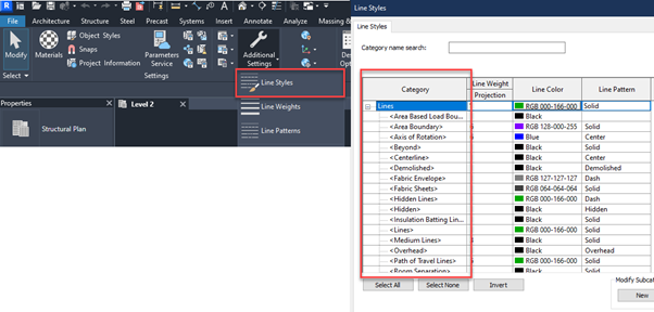
These are lines that are used in a project drawing to visually define the line appearances.
In Line Style, you can adjust the line weight, line colour and line pattern to enhance how a line will appear in your project drawing.
Examples of Line Styles in Revit include:
Area-Based Load Boundary: Defines the boundaries of area-based loads for structural analysis, marking zones that contribute to load calculations.
Area Boundary: Represents defined area boundaries, useful for zoning or space planning.
Axis of Rotation: Indicates rotational axes, often seen in mechanical engineering for components that pivot.
Beyond: Used to denote elements that extend beyond the visible portion of a drawing, like walls or beams stretching outside a view.
Centre-line: Marks the centre of elements like walls and columns, ensuring symmetrical alignment.
Demolished: Indicates elements slated for removal, especially useful in renovation plans.
Fabric Envelope and Fabric Sheets: Represent fabric boundaries, ideal for fabric structures.
Hidden Lines: Represent hidden elements.
Insulation Batting Lines: Show insulation material in assemblies, such as walls, roofs, or floors.
Overhead: Depict elements located above the current view, like overhead piping or ductwork.
Path of Travel Lines: Highlight the route or flow within a space, often used in safety or emergency planning.
Room Separation: Defines room boundaries in floor plans.
Sketch Lines: Used in creating conceptual designs.
Space Separation: Can be used to separate different areas within a project, probably depending on the use of the floor area.
Thin Lines and Wide Lines: Used for annotations and for feature emphasis.
Line Patterns in Revit
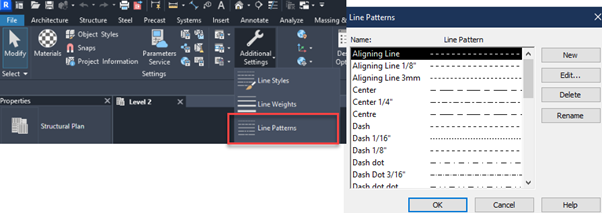
Line Patterns consist of a series of spaces, dashes and dots repeated over the length of the line.
Examples of Revit Line Patterns include:
Aligning Line: Used for aligning elements in a drawing to ensure accurate positioning of components.
Centre Line: Used in architectural and structural drawings to represent the centre of walls, columns and alignment of other structural elements.
Dash/Double Dash/Long Dash/Hidden: These are lines that are used to indicate hidden or not directly visible elements.
Dash Dot/Dash Dot Dot: Utilized in marking boundaries and to represent annotations
Demolished: Used in renovation plans to indicate items being removed.
Dot: Used in architectural drawings for annotations or to mark specific points or small features.
Gridline: Represents the grid layout for structures, essential in architectural and structural design for layout planning.
Loose Dash: Similar to a dash but with more space between the dashes, indicating a less significant element.
Overhead: Used to show elements located above the current view, such as overhead systems, e.g., ducts or piping
Rebar Cover Lines: Used in structural engineering to show the minimum cover required for rebar placement in concrete elements.
Triple Dash: Used in architectural and civil works for indicating auxiliary elements or features in a design.
Frequently Asked Questions:
What is the difference between Line Type and Line Patterns?
Line type refers to the category of line used, whereas line patterns refers to a repeated sequence made up of dots, dashes and spaces that controls how lines are drawn and hence affecting the visual appearance of lines.
How can I create new line styles?
Navigate to Manage Tab, click on Additional Settings option then select Line Styles and click on New to create your preferred line style.
Note: Line appearance can vary based on the following: view settings, visibility overrides and detail levels.
Can I customize Revit line weights and styles?
Absolutely, Yes!
Navigate to Manage Tab, click on Additional Settings option, then select either Line Weights or Line Styles depending on what you would want to modify.
How do I lock lines to other elements?
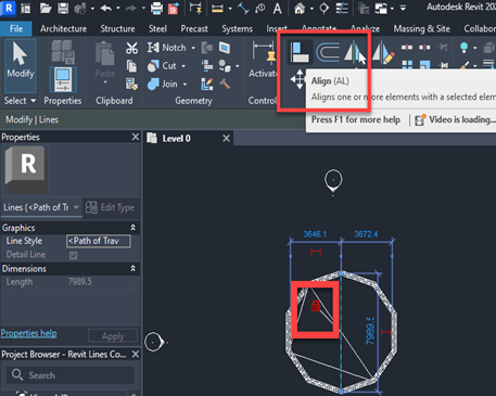
To lock lines with other elements, select the object you would like to align with, navigate to the Modify tab, then select the Align tool.
Click on the padlock symbol that appears next to the line to lock the line to an element.
How do I remove unnecessary lines in Revit?
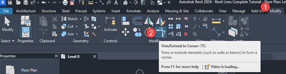
To remove or clean up excess lines, you can use the Trim or Delete tools.
Ensure to delete detail lines in the view where they were drawn.
Are Detail and Model Lines affected by visibility/graphics overrides?
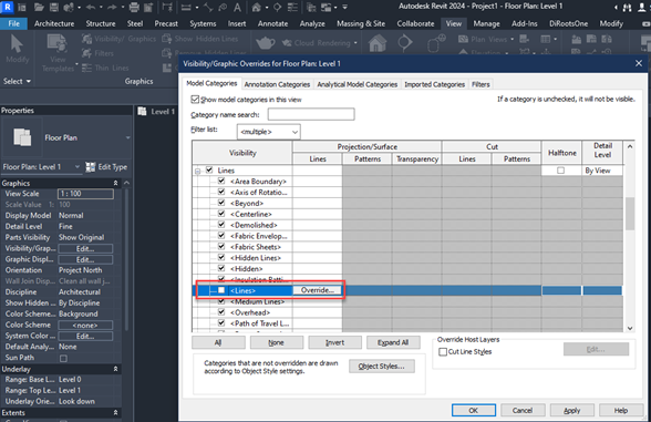
Both model and detail lines can be toggled on or off per view in the visibility/graphics settings.
To activate the Visibility/Graphics settings, use VG keyboard shortcut or in the Properties menu, select Edit in the Visibility/Graphics Overrides option.
Uncheck the lines you would like to hide/override in the project drawing.
Summary
Lines are the foundation of precise, clear, and effective communication in your Revit projects.
Understanding how to create, manipulate, and customize your model and detail lines for key structural elements or using detail lines for specific annotations can save you valuable time while improving the clarity and ensuring the quality of your project designs, drawings and documentation.
Practice with the guidelines shared here, and in the comment section below, let me know of any challenges with Lines In Revit.
Mastering using Revit Lines weights, styles and patterns enhances the clarity in your project drawings.
Which line weight, style or pattern make the most impact in your projects?
Comment with your insights or any questions.